EN DE
35
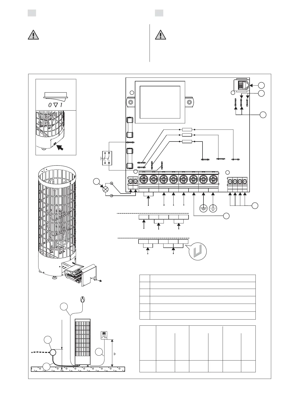
Figure 7. Electrical connections
Abbildung 7. Elektroanschlüsse
max. 500
A
C
D
B
3.3.3.
E
H
1 2 3 4 5 P GND GND
1 2 3 4
YELLOW
BLUE
WHITE
RED
X23
X21
X22 X9
X7
X13 X12 X11
SAFETY
GND
REMOTE
N L1 L2 L3
400 V
3 N ~
J
N
LIGHT
230 V
3 ~
1 2 3 4 5
L1
L1
L2
L3
1 2 3 4 5
N
230 V
1 N ~
R1
R2
R3
I
G
F
400 V 3N~ 230 V 3~ 230 V 1N~
A
A
A
6,9 5 x 1,5 3 x 10 4 x 2,5 3 x 20 3 x 10 1 x 35
9,0 5 x 2,5 3 x 16 4 x 4 3 x 25 3 x 10 1 x 50
kW
H07RN-F
min. mm²
H07RN-F
min. mm²
H07RN-F
min. mm²
E
F
G
H
I
J
Conn.
cable
Anschlus-
skabel
Output
Leistung
Fuse
Siche-
rung
Conn.
cable
Anschlus-
skabel
Conn.
cable
Anschlus-
skabel
Fuse
Siche-
rung
Fuse
Siche-
rung
Main switch
Hauptschalter
Control panel / Bedienfeld
Remote switch / Fernschalter
Safety switch / Sicherheitsschalter
Temperature sensor / Temperaturfühler
Lighting (max 100 W) / Beleuchtung (max. 100 W)
Control of electric heating / Steuerung der elektrischen Heizung
3.3. Electrical Connections
The heater may only be connected to the
electrical network in accordance with the
current regulations by an authorised, professional
electrician.
• The heater is semi-stationarily connected to the
junction box (figure 7: A) on the sauna wall.
The junction box must be splash-proof, and
3.3. Elektroanschlüsse
Der Anschluss des Saunaofens an das Strom-
netz darf nur von einem zugelassenen Elektro-
monteur unter Beachtung der gültigen Vorschriften
ausgeführt werden.
• Der Saunaofen wird halbfest an die Klemmdose
(Abb. 7: A) an der Saunawand befestigt. Die
Klemmdose muß spritzwasserfest sein und darf
 Loading...