The Hastings Hot Line Tools Digital Voltage Phase Meter, Catalog Number 6702, is an instruction manual for a device designed for use by trained personnel familiar with high voltage equipment. This device is specifically engineered for measuring digital voltage and phase in electrical systems.
Function Description
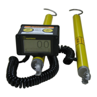
The Meter is used to measure AC and DC voltages in power systems. It consists of high voltage resistors encapsulated within two fiberglass housings, connected by a coiled cord. A digital display is attached to one of these housings. The device is designed to be used with an appropriate hot stick length for the potential being tested, ensuring user safety. It offers three modes of operation: AC, Hi-Pot, and DC. The Hi-Pot mode requires a specific Hi-Pot Adapter (Cat. No. 6702-2) to be installed. The Meter performs an auto self-test and battery voltage level check during startup, ensuring operational readiness.
Important Technical Specifications
- Line Voltage Mode:
- Operating Frequency: 50 – 60 Hz AC, DC
- Batteries: 3 x 1.5V Alkaline or NiMH “AA” cells
- Battery Life:
- 24 hours (backlight on continuously)
- 14 days (backlight off continuously)
- Operating Temperature: -40°F to 122°F
- Storage Temperature: -40°F to 158°F
- Weight:
- 3.8 lbs (without probes)
- 4.0 lbs (with probes)
- Accuracy:
- AC Scale: 2% of the reading ± 1 (number of least significant digits)
- DC Scale: ± 100 Volts
- Note: Accuracy can be affected by the proximity of other conductive objects.
Usage Features
-
Preparation:
- Remove the Meter from its storage case and inspect for damage.
- Attach each encapsulated resistor to a hot stick of appropriate length.
- For voltages over 40 kV, Extension Resistors (Cat. No. 6703) must be used. These are attached by removing the probes, attaching the Extension Resistors, and then re-assembling the probes. Extension Resistors are used in pairs, one on each end of the Meter sticks.
- The Meter automatically calibrates to the correct voltage range during startup if the ends of Extension Resistors remain in contact.
- Extension Resistor Pairs Required for Voltage Ranges:
- 1 pair: 80 kV
- 2 pairs: 120 kV
- 3 pairs: 160 kV
- 4 pairs: 200 kV
- 5 pairs: 240 kV
-
Self-Test:
- Turn the Meter on by pressing and releasing the ON/LIGHT/OFF button.
- Before powering on, ensure probe ends are in contact with each other.
- The Meter performs a self-test and battery voltage check.
- A "Battery Voltage: Low" message indicates batteries need replacement.
- The Meter defaults to AC mode upon power-on.
- If probe ends are not connected after self-test, the display will prompt for connection and pressing the AC/HIPOT/DC button to determine the number of Extension Resistors. The Meter defaults to 40 kV.
-
Backlight and Mode Selection:
- Press and hold the ON/LIGHT/OFF button to turn the backlight on or off.
- Press and hold the AC/HIPOT/DC button to access the mode selection menu.
- Pressing AC/HIPOT/DC repeatedly cycles through AC, Hi-Pot, and DC modes.
- The Hi-Pot mode requires the Hi-Pot Adapter (Cat. No. 6702-2) to be installed.
-
Voltage Measurement:
- When both probes contact a potential, the voltage is displayed numerically and graphically on the voltage bar graph.
- "++++" flashing indicates a voltage higher than the allowable range.
- "EEEE" flashing indicates the Meter is in the wrong mode for the power system being tested (e.g., AC mode on DC voltage, or Hi-Pot mode with AC/positive DC voltage without adapter).
-
Accessories:
- Extension Resistors (Cat. No. 6703): For systems above 40 kV.
- Underground Bushing Adapters:
- For 35 kV Elastimold and all 15/25 kV bushings (Cat. No. 6702-1).
- For 35 kV RTE bushings (Cat. No. 6702-3).
- These replace the supplied probes.
- DC Hi-Pot Adapter (Cat. No. 6702-2): Allows testing of underground cable by rectifying system voltage to charge the cable to a DC voltage equal to the peak AC voltage. It limits current to prevent fault currents if the cable is defective or grounded.
- WARNING: Do not use the Meter with a DC Hi-Pot Adapter installed when measuring on a DC power system, as it can block the DC voltage and prevent the Meter from displaying the system voltage.
-
Shutdown:
- To manually turn off, press and hold the ON/LIGHT/OFF button until the display shuts off. The backlight will turn on during shutdown.
- The Meter automatically shuts down after 40 minutes if no voltage potential is detected.
Maintenance Features
- Battery Replacement: The Meter uses three “AA” cells (Alkaline or NiMH). Batteries are accessed by removing the back panel of the Meter.
- Troubleshooting Guide:
- Meter will not turn on: Check batteries.
- Incorrect voltage range displayed: Manually turn Meter off, then turn back on ensuring free ends of Extension Resistors remain in contact during self-test.
- Display flashes "++++": Voltage higher than allowable range.
- Display flashes "EEEE": Meter is in the wrong mode for the power system being tested (e.g., AC mode on DC voltage, DC mode on AC voltage, AC mode with Hi-Pot Adapter on AC/positive DC voltage).
- Polarity incorrect on DC measurement: Meter is in Hi-Pot mode while applying to a DC power system.
Warranty
HASTINGS provides a one-year warranty from the date of purchase against manufacturing defects for the catalog number 6702 Digital Voltage Phase Meter. Defective units will be repaired or replaced at no cost. The warranty does not cover normal wear and tear, inappropriate use, alteration, or abuse. For warranty or repair, units should be sent to HASTINGS Hot Line Tools, 1301 W. Green St., Hastings, MI 49058, Attn: Warranty Repair Department. Technical assistance can be obtained by calling 269-945-9541 or faxing 269-945-4623.