Do you have a question about the Hatz Diesel 1D30 S and is the answer not in the manual?
Detailed diagrams of engine components with numerical labels.
Specifications for various engine models, including bore, stroke, capacity, and weight.
Explanation of information found on the engine's identification plate.
Schematic illustrating the engine's oil circulation system and components.
List of specialized tools and equipment required for maintenance and repair.
List of sealing and bonding agents used in assembly and repair, with codes.
Instructions for dismantling, inspecting, and assembling the fuel tank.
Details on dismantling, inspection, and assembly of fuel feed pumps.
Procedures for maintenance and replacement of oil bath air filters.
Instructions for servicing dry-type air filter elements and covers.
Guidelines for inspecting and maintaining service indicators and vacuum gauges.
Steps for dismantling, inspecting, and assembling pre-cleaners and cyclone air filters.
Procedures for fitting and replacing exhaust silencers and protection guards.
Instructions for inspecting, dismantling, and assembling standard and anti-kick-back starting handles.
Procedures for replacing worn guiding shells or bushings in starting handle supports.
Steps for dismantling, inspecting, and assembling cranking claws.
Detailed instructions for dismantling, inspecting, and assembling recoil starter systems.
Guidelines for dismantling, inspecting, and assembling starter motors, including electrical connections.
Procedures for checking and replacing magnet segments on the flywheel.
Instructions for fixing and adjusting air gaps for alternator coils using spacers.
Instructions for inspecting, dismantling, and fitting starter ring gears onto the flywheel.
Procedures for retrofitting and replacing lubrication oil filters and strainers.
Information on additional oil sumps to increase oil change intervals.
Detailed instructions for adjusting low idle speed stabilization for precise governing.
Procedures for dismantling, inspecting, and assembling stop levers for engine control.
Explanation of the mechanical shut-off device for preventing engine damage due to low lubrication.
Steps for removing and assembling adaptor housings, including starter motor removal.
A matrix showing which parts can be disassembled together.
Instructions for installing oil spray nozzles and fitting main and camshaft bearings.
Details on fitting various plugs into the crankcase, considering fuel pump presence.
Procedures for dismantling, inspecting, and assembling crankshaft thrust plates and cam followers.
Instructions for removing and assembling the oil sump and suction sieve.
Specific assembly instructions for the oil sump on 1D50 engines, including cowling.
Procedures for checking base plate flatness and replacing the oil pressure relief valve.
Information on using sealing caps for cylinder head screws to prevent corrosion.
Table of wear and grinding dimensions for crankshaft journals and bearing surfaces.
Instructions for removing, heating, and fitting crankshaft gearwheels and stubshafts.
Procedures for replacing crankshaft wear sleeves and closing covers.
Specific instructions for bearing flange assembly on 1D90V/W engines and crankshaft axial clearance adjustment.
Procedures for dismantling, inspecting, and assembling the camshaft.
Steps for dismantling, inspecting, and assembling the balancer unit with drive gears.
Instructions for removing, inspecting, and assembling piston rings and pistons.
Procedures for dismantling, inspecting, and assembling connecting rods and big end bearings.
Instructions for checking cylinder condition and performing re-honing if necessary.
Procedures for dismantling, assembling, and adjusting rockers and the decompression device.
Guidelines for checking and setting the piston-to-valve clearance (bumping clearance).
Instructions for removing and assembling the cylinder head and oil supply pipe.
Procedures for checking valve recession, radial play, and replacing valve guides.
Instructions for dismantling, inspecting, and assembling the cylinder head cover and its breather system variants.
Procedures for removing and installing pushrod tubes and protection tubes, and checking related components.
Detailed steps for dismantling, inspecting, and assembling the oil pump and governor unit.
Instructions for timing cover removal/assembly, noting modifications and oil gallery differences.
Explanation of the function and procedures for the standard extra fuel device.
Description of the thermally activated extra fuel device and its operation based on oil temperature.
Instructions for dismantling, inspecting, and assembling the fuel pressure pipe.
Procedures for testing, dismantling, and assembling fuel injectors, including nozzle checks.
Guidelines for functional checks, timing adjustments, and fuel quantity settings for the injection pump.
Instructions for removing, inspecting, and assembling roller tappets and related components.
Steps for removing, inspecting, and installing the flywheel, including timing marks.
Instructions for handling cowling and air duct systems, considering variants and ensuring proper cooling.
Procedures for inspecting and servicing breather systems, covering different versions.
Details on different speed control system versions, their suitability, and conversion procedures.
Steps for accessing and removing/installing engine capsule components and internal air ducting.
Table of injection pump timing and pressure settings across various engine models and speeds.
Data on governor spring dimensions for different engine types and applications.
Table showing required bumping clearance values for different engine types.
Table detailing nominal and maximum valve recession measurements for various engine types.
Table specifying cold tappet clearance for inlet and outlet valves on different engine models.
Visual guide and specifications for measuring crankshaft end-float.
Visual guide and specifications for setting alternator air gaps.
Table showing lubricant oil quantities in liters and US quarts for different engine series.
Table of oil pressure specifications in bar and psi at various engine speeds.
Table of torque values (Nm and lbf ft) for various fasteners across different engine models.
List of codes and their corresponding designations for electrical components in circuit diagrams.
Table listing terminal designations and their corresponding electrical functions or components.
Diagrams showing connector pin assignments for engines and wiring harnesses.
Electrical schematic showing system components, connections, and functions with display.
Electrical schematic detailing the system with display and starter protection module.
Electrical schematic for systems with automatic shut-down and starter protection.
Electrical schematic for systems featuring automatic start and stop functions.
Electrical schematic illustrating the instrument box functions and connections with display.
Electrical schematic for instrument boxes with automatic pre-heat and shut-down systems.
Electrical schematic showing instrument box, display, and power box integration.
Electrical schematic for instrument box with pre-heat/shut-down and power box systems.
Wiring diagrams for testing alternator charging current and no-load voltage.
Charging current and no-load voltage data for 12V alternators with open coils.
Charging current and no-load voltage data for 24V alternators with open coils.
General troubleshooting chart for electrical system issues.
Chart for diagnosing and resolving battery malfunctions, including charging and overcharging issues.
Chart for diagnosing and resolving issues with the starter motor not rotating or engaging.
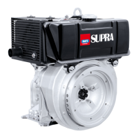
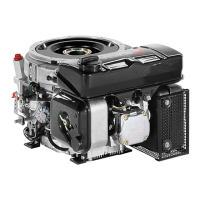
| Engine Model | 1D30 S |
|---|---|
| Manufacturer | Hatz Diesel |
| Bore | 82 mm |
| Width | 420 mm |
| Cooling System | Air-cooled |
| Fuel Type | Diesel |
| Engine Type | Single-cylinder, four-stroke diesel engine |
| Starting System | Recoil starter |