EasyManua.ls Logo

HAWE Hydraulik KA - User Manual

HAWE Hydraulik KA
28 pages
Print Icon
To Next Page IconTo Next Page
Loading...
Compact hydraulic power packs type KA and KAW
for short-term and intermittent service
for 3+ and 1+phase power supply, as single or dual circuit pumps
D 8010
Compact power pad
KA and KAW
December 2011-00© 2006 by HAWE Hydraulik
HAWE HYDRAULIK SE
STREITFELDSTR. 25 • 81673 MÜNCHEN
1.1
Flow Q
max
= 19.9 lpm (1450 rpm)
Operating pressure p
max
= 700 bar
Additional information:
Compact hydraulic power packs type KA 4 D 8010-4
type HC D 7900
type HCG D 7900 G
type NPC D 7940
type MPN D 7207
type HK D 7600 ++
; Tank with pressed in stator
< Fluid filling / breather
= Terminal box or alternatively: Version with plug Co. HARTING
> Connection pedestal with one (single circuit pump) or two
pressure ports (dual circuit pump) and one return port.
Prepared for the mounting of connection blocks for ongoing
pressure and reflow pipes or with directly mounted directional
valve banks (see D 6905 ++).
1. Design and general information
Order example
KA 24 ST/H 0,66
- A 2/650
- VB 11 FM-H 3 N 3-1-N 24-
3x400 V 50 Hz
1.1 Basic design
The compact hydraulic power pack type KA serves to
supply pressurized fluid for intermittently or short-term
operated hydraulic circuits.
The basic hydraulic power pack consists:
o the tank (available in different sizes)
o the drive motor (available for different voltages and power
requirements)
o the radial piston or gear pump directly driven by the
motor shaft
The compact style obtained with this design represents an
essential advantage opposite conventional units.
Complete turn-key solutions can be easily arranged via a
wide range of connection blocks (see D 6905 ++) and
directly mountable valve banks (see photo).
There is a wide field of applications for theses compact
power packs within tool machines, jig assemblies and
general mechanical engineering.
The power pack is suited for operation modes S2 (short
time service) and S3 (intermittent service). The load can be
up to 1.8 of the nom. power rating during these operation
modes.
Table of contents
1. General information ......................................1
1.1 Basic design ..................................................................... 1
2. Available versions ......................................... 2
2.1 Motor and tank section .................................................... 2
2.2 Pump section.................................................................... 4
2.2.1 Single circuit pumps ......................................................... 4
2.2.2 Dual circuit pumps ........................................................10
3. Additional parameters .................................11
3.1 General .............................................................................11
3.2 Hydraulic ........................................................................... 12
3.3 Electrical .......................................................................... 12
4. Dimensions .................................................. 16
4.1 Mounting hole pattern ...................................................... 16
4.2 Basic pump ....................................................................... 17
4.3 Electrical and hydraulic connections ................................ 20
5. Appendix ...................................................... 22
5.1 Notes regarding selection................................................ 22
5.2 Assembly and installation notes ........................................ 26
5.3 Servicing ........................................................................... 28
5.4 Declaration of conformity ................................................. 28
;
<
=
>
Question and Answer IconNeed help?

Do you have a question about the HAWE Hydraulik KA and is the answer not in the manual?

Overview

This document describes the HAWE Compact Hydraulic Power Packs, type KA and KAW, designed for short-term and intermittent service. These power packs are suitable for 3-phase and 1-phase power supplies and can be configured with single or dual circuit pumps.

Function Description

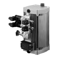
The HAWE Compact Hydraulic Power Pack, type KA, is engineered to supply pressurized fluid to hydraulic circuits that operate intermittently or for short durations. The basic unit comprises a tank (available in various sizes), a drive motor (with different voltage and power requirements), and a radial piston or gear pump directly driven by the motor shaft. This compact design offers a significant advantage over conventional units, allowing for easy integration into complete turn-key solutions through a wide range of connection blocks and directly mountable valve banks. These power packs find extensive applications in tool machines, jig assemblies, and general mechanical engineering. They are designed for operation modes S2 (short-time service) and S3 (intermittent service), capable of handling loads up to 1.8 times their nominal power rating during these modes.

For dual circuit pump versions, the power pack can be configured with two radial piston pumps (HH) or a radial piston pump and a gear pump (HZ), each with its own pressure connection (P1 and P3).

Important Technical Specifications

Flow and Pressure:

  • Maximum flow (Qmax): 19.9 lpm (at 1450 rpm).
  • Maximum operating pressure (Pmax): 700 bar.
  • The delivery flow rating (Qpu) is a guideline figure, based on nominal revolution rating, which may slightly decrease depending on the load.
  • The maximum permissible hydraulic work (pVg)max for versions with gear pumps (Z, HH, HZ) must be reduced by 10%.
  • Versions with 3-phase motors can start against maximum pressure, while 1-phase motors can only start against slight pressure.

Motor Data:

  • Available in 3-phase and 1-phase configurations with various nominal powers and speeds.
  • Nominal voltages for 3-phase motors include 400/230V, 460/265V, 690V, 200V, 500V, and 575V, at 50 Hz or 60 Hz.
  • Nominal voltages for 1-phase motors include 230V and 110V, at 50 Hz or 60 Hz.
  • The current consumption of the motor is highly dependent on its load. Nominal figures apply strictly to one operating point.
  • The actual current consumption for 1-phase motors also depends on the size of the operating capacitor, which is not included in the scope of delivery.
  • Tension tolerances: ±10% (IEC 38), with ±5% for 3 x 460/265V 60 Hz.

Hydraulic Fluid:

  • Hydraulic oil conforming to DIN 51 524 part 1 to 3; ISO VG 10 to 68 conforming to DIN 51 519.
  • Optimal operation range: Radial piston pump H: 10...500 mm²/s; Gear pump Z: 20...100 mm²/s.
  • Viscosity range: min. approx. 4 mm²/s; max. approx. 800 mm²/s.
  • Biologically degradable pressure fluids type HEES (synthetic ester) are also suitable at service temperatures up to approx. +70°C.
  • Electrically hazardous: Any fluid types containing water must not be used (short-circuit).

Temperature:

  • Ambient temperature range: approx. -40...+80°C.
  • Fluid temperature range: -25...+80°C.
  • Permissible temperature during start: -40°C (observe start-viscosity), provided the service temperature is at least 20K higher for subsequent operation.
  • For biologically degradable pressure fluids, observe manufacturer's specifications and compatibility with seal material, not exceeding +70°C.
  • The persistent service temperature is reached after approximately one hour of operating time.
  • The persistent over-temperature can be reduced by 15% with tanks coding 02, 2, 22, 3, and by 50% when utilizing an auxiliary blower (coding F or F1).

Tank Sizes and Filling Volumes:

  • Various tank sizes are available, offering different filling volumes (Vfill) and usable filling volumes (Vusable) for both vertical and horizontal installations.
  • For example, tank size "no coding" has a filling volume of 3.9 l and usable volumes of 1.85 l (vertical) and 1.5 l (horizontal).
  • Tank size "3" has a filling volume of 11.1 l and usable volumes of 8.95 l (vertical) and 4.8 l (horizontal).

Electrical Connection and Protection:

  • Connection options include plug Co. HARTING (cable 1.5 mm²) or integrated terminal box with blade type plugs 6.3 Co. AMP.
  • Protection class: IP 65 according to IEC 60529.
  • Safety class: DIN VDE 0100 safety class 1.
  • Insulation layout conforms to EN 60 664-1.
  • Suppressors (Type RC3R) are available for 3x 575V AC, 10...400 Hz, 4.0 kW.
  • Optional auxiliary blower (coding F, F1) with motor data for 1x230V 50/60 Hz (45W), 1x110V 60 Hz (38W), and 24V DC (12W).
  • Temperature switch (coding T, T60) with trigger points at 80°C (standard with KAW) or 60°C (only with KA).
  • Float switch (coding S, D, KS, KD) for horizontal and vertical versions, with NO-contact or NC-contact.

Physical Characteristics:

  • Mass (without fluid) varies by type and pump elements, e.g., KA 21, 23 (H 3 cyl.) is 10.9 kg, KA 26, 28 (Z) is 16.5 kg.
  • Additional mass for tank sizes: +0.7 kg for size 01, 1; +4.4 kg for size 22, 3.
  • Auxiliary blower adds +1.8 kg.
  • Running noise levels are provided in diagrams as a function of hydraulic work (pVg).

Usage Features

Installation Positions:

  • Can be installed vertically (KA...S) or horizontally (KA...L).
  • The vertical version using radial piston pumps (H, HH, HZ) must not be installed horizontally.
  • For horizontal versions installed vertically, the breather must be positioned on top and the pump at the bottom.

Connection Blocks and Valve Banks:

  • Connection blocks (types A, AL, AM, AK, AS, AV, AP, AN, AL, NA, C30, SS, VV, AX, B, C) are mandatory for hydraulic connections, offering various functionalities like pressure limiting valves, filters, idle circulation valves, and accumulator charging valves.
  • Directional valve banks (VB, BWN, BWH, BVZP, SWR, SWS, BA, BVH, NBVP, NSWP, NSMD, NZP) can be directly mounted to connection blocks, creating compact hydraulic units without additional piping.

Motor Protective Switch:

  • The motor protective switch should be set to approximately 0.7 times the nominal current (IM). This ensures that the bimetallic switch does not trigger too early during normal operation, but also prevents the oil temperature from rising too high due to prolonged response time after the pressure limiting valve is in action.
  • It is recommended to test the setting of the motor protective switch during a test run. Temperature switches, float switches, and pressure switches serve as additional safety measures.

Electromagnetic Compatibility (EMC):

  • No impermissible spikes are emitted when hydraulic power packs (inductive motors) are connected to a system conforming to EN 60034-1.
  • Electromagnetic fields may be generated during motor switching, which can be minimized using a filter (e.g., type 23140, 3x400V AC 4kW 50-60 Hz).
  • An optional suppressor (coding E or PE) can be directly mounted at the terminal box or plug Co. HARTING for type KA.

Maintenance Features

General Servicing:

  • The hydraulic power packs and directly mounted valves are almost maintenance-free.
  • The fluid level should be checked regularly, depending on operating conditions.
  • The hydraulic fluid should generally be replaced annually, or more frequently if tests indicate aging or contamination.
  • Filters (pressure or return) should be replaced accordingly.

Silica Gel Filters:

  • If present, silica gel filters should be checked visually every 6 months for a color change.
  • Blue indicates "OK," while red indicates "Replacement is indicated."
  • Used silica gel filters must be disposed of as hazardous waste.

Safety Precautions for Maintenance:

  • Before any maintenance or repair work, the system must be depressurized (hydraulic side), especially for systems with hydraulic accumulators.
  • The system must be cut-off or de-energized.

Repairs and Spare Parts:

  • Repairs (replacing service items) can be performed by competent craftsmen.
  • The motor cannot be repaired or replaced by the customer. If the motor is defective, the complete pump should be returned to HAWE facilities for an overhaul.
  • Spare parts lists are available upon request; specify the pump type according to the type plate on the pump or cover plate.

HAWE Hydraulik KA Specifications

General IconGeneral
BrandHAWE Hydraulik
ModelKA
CategoryPower Pack
LanguageEnglish