is the starter wire. Crank the vehicle. The meter should ONLY show 12V when the key is in the
crank position. There should be 0 volts in all other positions. Starter Wires are used in Remote Car
Starter Installations.
Using the above testing guidelines, you can test any wire. When testing an accessory like a horn or
dome light in the vehicle, simply activate the accessory with your meter leads in place to get the
meter reading. The meter should only read power and ground on accessory items when they are
activated.
Install Your HAWK compact Motorcycle Alarm System
LOCATION OF MAIN SYSTEM COMPONENTS
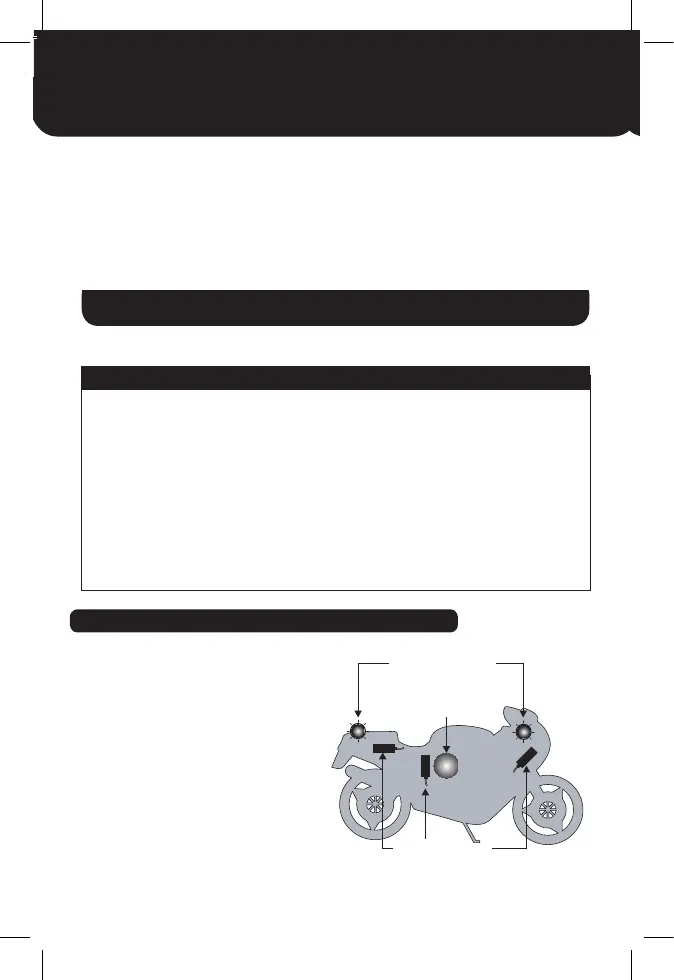
Before commencing with the installation,
plan where to secure the main components.
See the location diagram for suggested
locations for the main components
of the system.
q 4HE#ONTROL5NIT q 0LIERS#ABLE#UTTERS
q 4WO2EMOTE4RANSMITTERS q -OTORCYCLEWIRINGDIAGRAM
q )NSTALLATION)NSTRUCTION q $RILLMMMMBITS
q 5SER'UIDE q 3OLDERING%QUIPMENT
q 3IREN q 3ELF!DHESIVE(EATSINK4UBING
q 7IRING,OOM q 'OODQUALITYINSULATINGTAPE
q 7ARRANTY)NFORMATION q -ASKING4APE
q !LARM7ARNING3TICKER
q .ECK3TRAP
q -ULTIMETER
q 'ENERAL7ORKSHOP4OOLS
/iÊÝÊÌ>ÃÊ /ÃÊ,iµÕÀi`\
",ÊÊ,Ê /",
-1-/Ê-1,Ê /,Ê,
",ÊÊ" /" -Ê/"
"/",9Ê7, Ê""
-1-/Ê"/" -
",Ê" /,"Ê1 /
2ED 0OSITIVE 2ED 2ED 2ED
'REENX .EGATIVE 'REEN "LACK7HITE "LACK
/RANGE )NDICATOR /RANGE $ARK'REEN $ARK'REEN
,IGHT"LUE )NDICATOR ,IGHT"LUE "LACK $ARK"ROWN
"LACK2ED )GNITIONPOSITIVE "LACK /RANGE "ROWN
'REY )MMOBILISER
7HITE"LACK )MMOBILISER
"LACK7HITE )MMOBILISER
9ELLOW2ED 2EMOTE3TART 9ELLOW2ED 9ELLOW'REEN "LUE7HITE
>LiÃÊvÊ8xäÊ ÕVÌÊ " Ê -1<1Ê 9
ÊÜÀ}Ê`>}À>ÊvÊÛ>ÀÕÃÊLiÃÊ}Õ`>ViÊÞ®°
5
MOUNTING CONTROL UNIT
The control Unit should be located in a protected environment with good access to the motorcycle
wiring loom. Avoid extremes of heat i.e. exhaust engine and direct exposure to the elements, and
make sure that the unit does not interfere with normal operation of the motor cycle. Suggested loca-
tions under the seat or behind the seat are usually the best locations. The control wiring must point
down to avoid any water ingress.
MOUNTING THE SIREN
Ensure that the siren is not installed in a position prone to excessive heat, water or mud splashes!
The siren should be facing slightly down so that water will not pool. Fasten the Siren in place using
double sided tape provided with the alarm. Prior to applying the double sided tape, clean the af-
fected surfaces with a suitable cleanser that will remove any dirt and grease. The siren plugs directly
into its mating connector of the alarm harness for easy installation.
LED ALARM INDICATOR
The desired location of the LED Alarm Indicator should be mounted in a prominent position; sug-
gested locations are the instrument cluster or a rear body panel with good viewing access.
INSTALLATION OF MAIN SYSTEM COMPONENTS
Great care has been take in the design and manufacture of HAWK products, Correct installation and good
working practices will enhance the operation of the alarm system and give long term benefit to the user.
1. position and attach the Control unit
2. position and attach the LED Alarm indicator
ALARM WIRING
Plan where to make the connections to the motorcycle wiring loom. The alarm loom should run
alongside the original motorcycle loom taking full advantage of the motorcycle wiring loom integ-
rity. Normally all connections can be made to a central area on the motorcycle loom, such as under
the petrol tank.
NOTE: Soldered joints are recommended for all wiring connections.
q 4HE#ONTROL5NIT q 0LIERS#ABLE#UTTERS
q 4WO2EMOTE4RANSMITTERS q -OTORCYCLEWIRINGDIAGRAM
q )NSTALLATION)NSTRUCTION q $RILLMMMMBITS
q 5SER'UIDE q 3OLDERING%QUIPMENT
q 3IREN q 3ELF!DHESIVE(EATSINK4UBING
q 7IRING,OOM q 'OODQUALITYINSULATINGTAPE
q 7ARRANTY)NFORMATION q -ASKING4APE
q !LARM7ARNING3TICKER
q .ECK3TRAP
q -ULTIMETER
q 'ENERAL7ORKSHOP4OOLS
/iÊÝÊÌ>ÃÊ /ÃÊ,iµÕÀi`\
* Ê/Ê -//"
2ED 0OSITIVE 2ED 2ED 2ED
'REENX .EGATIVE 'REEN "LACK7HITE "LACK
/RANGE )NDICATOR /RANGE $ARK'REEN $ARK'REEN
,IGHT"LUE )NDICATOR ,IGHT"LUE "LACK $ARK"ROWN
"LACK2ED )GNITIONPOSITIVE "LACK /RANGE "ROWN
'REY )MMOBILISER
7HITE"LACK )MMOBILISER
"LACK7HITE )MMOBILISER
9ELLOW2ED 2EMOTE3TART 9ELLOW2ED 9ELLOW'REEN "LUE7HITE
>LiÃÊvÊ8xäÊ ÕVÌÊ " Ê -1<1Ê 9
ÊÜÀ}Ê`>}À>ÊvÊÛ>ÀÕÃÊLiÃÊ}Õ`>ViÊÞ®°
4
is the starter wire. Crank the vehicle. The meter should ONLY show 12V when the key is in the
crank position. There should be 0 volts in all other positions. Starter Wires are used in Remote Car
Starter Installations.
Using the above testing guidelines, you can test any wire. When testing an accessory like a horn or
dome light in the vehicle, simply activate the accessory with your meter leads in place to get the
meter reading. The meter should only read power and ground on accessory items when they are
activated.
Install Your HAWK compact Motorcycle Alarm System
LOCATION OF MAIN SYSTEM COMPONENTS
Before commencing with the installation,
plan where to secure the main components.
See the location diagram for suggested
locations for the main components
of the system.
q 4HE#ONTROL5NIT q 0LIERS#ABLE#UTTERS
q 4WO2EMOTE4RANSMITTERS q -OTORCYCLEWIRINGDIAGRAM
q )NSTALLATION)NSTRUCTION q $RILLMMMMBITS
q 5SER'UIDE q 3OLDERING%QUIPMENT
q 3IREN q 3ELF!DHESIVE(EATSINK4UBING
q 7IRING,OOM q 'OODQUALITYINSULATINGTAPE
q 7ARRANTY)NFORMATION q -ASKING4APE
q !LARM7ARNING3TICKER
q .ECK3TRAP
q -ULTIMETER
q 'ENERAL7ORKSHOP4OOLS
/iÊÝÊÌ>ÃÊ /ÃÊ,iµÕÀi`\
* Ê/Ê -//"
-1-/Ê"/" -
",ÊÊ,Ê /",
-1-/Ê-1,Ê /,Ê,
",ÊÊ" /" -Ê/"
"/",9Ê7, Ê""
-1-/Ê"/" -
",Ê" /,"Ê1 /
2ED 0OSITIVE 2ED 2ED 2ED
'REENX .EGATIVE 'REEN "LACK7HITE "LACK
/RANGE )NDICATOR /RANGE $ARK'REEN $ARK'REEN
,IGHT"LUE )NDICATOR ,IGHT"LUE "LACK $ARK"ROWN
"LACK2ED )GNITIONPOSITIVE "LACK /RANGE "ROWN
'REY )MMOBILISER
7HITE"LACK )MMOBILISER
"LACK7HITE )MMOBILISER
9ELLOW2ED 2EMOTE3TART 9ELLOW2ED 9ELLOW'REEN "LUE7HITE
>LiÃÊvÊ8xäÊ ÕVÌÊ " Ê -1<1Ê 9
ÊÜÀ}Ê`>}À>ÊvÊÛ>ÀÕÃÊLiÃÊ}Õ`>ViÊÞ®°
5
MOUNTING CONTROL UNIT
The control Unit should be located in a protected environment with good access to the motorcycle
wiring loom. Avoid extremes of heat i.e. exhaust engine and direct exposure to the elements, and
make sure that the unit does not interfere with normal operation of the motor cycle. Suggested loca-
tions under the seat or behind the seat are usually the best locations. The control wiring must point
down to avoid any water ingress.
MOUNTING THE SIREN
Ensure that the siren is not installed in a position prone to excessive heat, water or mud splashes!
The siren should be facing slightly down so that water will not pool. Fasten the Siren in place using
double sided tape provided with the alarm. Prior to applying the double sided tape, clean the af-
fected surfaces with a suitable cleanser that will remove any dirt and grease. The siren plugs directly
into its mating connector of the alarm harness for easy installation.
LED ALARM INDICATOR
The desired location of the LED Alarm Indicator should be mounted in a prominent position; sug-
gested locations are the instrument cluster or a rear body panel with good viewing access.
INSTALLATION OF MAIN SYSTEM COMPONENTS
Great care has been take in the design and manufacture of HAWK products, Correct installation and good
working practices will enhance the operation of the alarm system and give long term benefit to the user.
1. position and attach the Control unit
2. position and attach the LED Alarm indicator
ALARM WIRING
Plan where to make the connections to the motorcycle wiring loom. The alarm loom should run
alongside the original motorcycle loom taking full advantage of the motorcycle wiring loom integ-
rity. Normally all connections can be made to a central area on the motorcycle loom, such as under
the petrol tank.
NOTE: Soldered joints are recommended for all wiring connections.
q 4HE#ONTROL5NIT q 0LIERS#ABLE#UTTERS
q 4WO2EMOTE4RANSMITTERS q -OTORCYCLEWIRINGDIAGRAM
q )NSTALLATION)NSTRUCTION q $RILLMMMMBITS
q 5SER'UIDE q 3OLDERING%QUIPMENT
q 3IREN q 3ELF!DHESIVE(EATSINK4UBING
q 7IRING,OOM q 'OODQUALITYINSULATINGTAPE
q 7ARRANTY)NFORMATION q -ASKING4APE
q !LARM7ARNING3TICKER
q .ECK3TRAP
q -ULTIMETER
q 'ENERAL7ORKSHOP4OOLS
/iÊÝÊÌ>ÃÊ /ÃÊ,iµÕÀi`\
* Ê/Ê -//"
2ED 0OSITIVE 2ED 2ED 2ED
'REENX .EGATIVE 'REEN "LACK7HITE "LACK
/RANGE )NDICATOR /RANGE $ARK'REEN $ARK'REEN
,IGHT"LUE )NDICATOR ,IGHT"LUE "LACK $ARK"ROWN
"LACK2ED )GNITIONPOSITIVE "LACK /RANGE "ROWN
'REY )MMOBILISER
7HITE"LACK )MMOBILISER
"LACK7HITE )MMOBILISER
9ELLOW2ED 2EMOTE3TART 9ELLOW2ED 9ELLOW'REEN "LUE7HITE
>LiÃÊvÊ8xäÊ ÕVÌÊ " Ê -1<1Ê 9
ÊÜÀ}Ê`>}À>ÊvÊÛ>ÀÕÃÊLiÃÊ}Õ`>ViÊÞ®°
21
CONNECTING THE ALARM WITH SPECIFIC T HARNESS
(OPTIONAL EXTRAS)
 Loading...