6
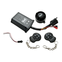
ALARM WIRING INSTALLATION
IMPORTANT
Make sure that you have planned the wiring connections before adapting / cutting the alarm loom or
the motorcycle loom.
1. Connect RED wire to constant power input (+) 12v supply from the battery.
2. Connect BLACK/RED wire to any wire in the ignition system which becomes live when
the ignition is switched ON, and remains live when the starter is pressed e.g. power feed
from ignition switch to fuse box.
3. Connect ORANGE wire to left indicator positive (+) lead output. Take care not to use
the motorcycle indicator negative (-) wire.
4. Connect LIGHT BLUE wire to right indicator positive (+) output. Take care not to use
the motorcycle indicator negative (-) wire.
5. Connect YELLOW/RED wire to the remote starter (+) switch.
6. Engine immobilisation- there is 3 cables 1) BLACK/WHITE wire 2) WHITE/BLACK
wire 3) Grey. Please see pages 12-15 for installation. Recommended circuits
are the starter motor or fuel pump relay. (The CPU on Italian motorcycles or the
Hall Effect ignition on Harley Davidsons is not recommended.)
7. Connect 2 x GREEN earth wires to the motorcycle frame or the battery negative terminal.
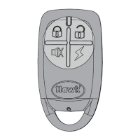
8. Connect small 2 pin connector to LED
9. Blue/White wire for optional negative input sensor e.g. tilt or microwave sensor applicable to X50
10. Connect large 2 pin connector to Siren
ATTENTION: Commercial Electronics always suggests installation be performed by a certified and
trained installation technician, professional installation is requirement to obtain full warranty. This
wiring information is being provided free of charge and on an “as is” basis, without any representation
or warranty to the products being installed. It is your responsibility to insure proper installation. Com-
mercial Electronics assumes no responsibility with regards to the accuracy or currency of this infor-
mation. Proper installation in every case is and remains the responsibility of the installer. Commercial
Electronics assumes no responsibility resulting from an improper installation, even in reliance upon
this information. Any harm or injury to the installer is in no way the responsibility of Commercial
Electronics. Any damage to the vehicle during installation or after installation is not the responsibility
of Commercial Electronics.
6
ALARM WIRING INSTALLATION
IMPORTANT
Make sure that you have planned the wiring connections before adapting / cutting the alarm loom or
the motorcycle loom.
1. Connect RED wire to constant power input (+) 12v supply from the battery.
2. Connect BLACK/RED wire to any wire in the ignition system which becomes live when
the ignition is switched ON, and remains live when the starter is pressed e.g. power feed
from ignition switch to fuse box.
3. Connect ORANGE wire to left indicator positive (+) lead output. Take care not to use
the motorcycle indicator negative (-) wire.
4. Connect LIGHT BLUE wire to right indicator positive (+) output. Take care not to use
the motorcycle indicator negative (-) wire.
5. Connect YELLOW/RED wire to the remote starter (+) switch.
6. Engine immobilisation- there is 3 cables 1) BLACK/WHITE wire 2) WHITE/BLACK
wire 3) Grey. Please see pages 12-15 for installation. Recommended circuits
are the starter motor or fuel pump relay. (The CPU on Italian motorcycles or the
Hall Effect ignition on Harley Davidsons is not recommended.)
7. Connect 2 x GREEN earth wires to the motorcycle frame or the battery negative terminal.
8. Connect small 2 pin connector to LED
9. Blue/White wire for optional negative input sensor e.g. tilt or microwave sensor applicable to X50
10. Connect large 2 pin connector to Siren
ATTENTION: Commercial Electronics always suggests installation be performed by a certified and
trained installation technician, professional installation is requirement to obtain full warranty. This
wiring information is being provided free of charge and on an “as is” basis, without any representation
or warranty to the products being installed. It is your responsibility to insure proper installation. Com-
mercial Electronics assumes no responsibility with regards to the accuracy or currency of this infor-
mation. Proper installation in every case is and remains the responsibility of the installer. Commercial
Electronics assumes no responsibility resulting from an improper installation, even in reliance upon
this information. Any harm or injury to the installer is in no way the responsibility of Commercial
Electronics. Any damage to the vehicle during installation or after installation is not the responsibility
of Commercial Electronics.
21
CONNECTING THE ALARM WITH SPECIFIC T HARNESS
(OPTIONAL EXTRAS)
 Loading...