8
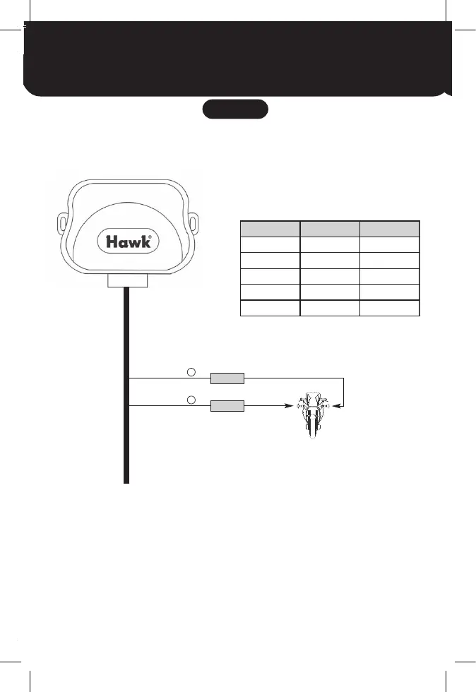
1. Locate the left and right indicator wires at the rear of bike are usually
easiest to wire up.
2. Connect orange wire to the left positive (+) indicator feed.
3. Connect light blue wire right positive (+) indicator feed.
Take care not to use the motorcycle indicator negative (-) wire.
STEP 2
Connecting the Orange & Light Blue wires
5A fuse
ORANGE
LIGHT BLUE
5A fuse
+
+
LEFT
INDICATOR
RIGHT
INDICATOR
Left IndicatorBike Right Indicator
Honda Orange wire Light Blue wire
Kawasaki Green wire Grey wire
Suzuki Green or Black Grey wire
Yamaha Green wire Brown wire
Harley Davidson Brown wire Purple wire
9
This wire must be connected to wire that gives positive (+) 12 volt when the ignition
key is turned on and this wire should not show any voltage when ignition turned off.
NOTE: However there may be more than one wire, make sure you have the correct
ignition feed.
NOTE: This wire can be located at the main ignition switch below.
Now:
1. Connect siren to alarm system
2. Connect LED to alarm system
3. Put fuse into alarm fuse holder (RED wire)
At this point test the alarm and make sure it is working.
For advance features i.e. immobiliser or remote start, see pages 12-16.
IGNITION SWITCH WIRES
STEP 3
Connecting the Black wire
Ignition SwitchBike
Honda Black/Red wire
Kawasaki Brown wire
Suzuki Orange wire
Yamaha Brown wire
BLACK/RED
INDICATOR WIRES
STEP 2
Connecting the Orange & Light Blue wires
5A fuse
ORANGE
LIGHT BLUE
5A fuse
+
+
LEFT
INDICATOR
RIGHT
INDICATOR
Left IndicatorBike Right Indicator
Honda Orange wire Light Blue wire
Kawasaki Green wire Grey wire
Suzuki Green or Black Grey wire
Yamaha Green wire Brown wire
Harley Davidson Brown wire Purple wire
7.5A fuse
7.5A fuse
8
1. Locate the left and right indicator wires at the rear of bike are usually
easiest to wire up.
2. Connect orange wire to the left positive (+) indicator feed.
3. Connect light blue wire right positive (+) indicator feed.
Take care not to use the motorcycle indicator negative (-) wire.
INDICATOR WIRES
STEP 2
Connecting the Orange & Light Blue wires
5A fuse
ORANGE
LIGHT BLUE
5A fuse
+
+
LEFT
INDICATOR
RIGHT
INDICATOR
Left IndicatorBike Right Indicator
Honda Orange wire Light Blue wire
Kawasaki Green wire Grey wire
Suzuki Green or Black Grey wire
Yamaha Green wire Brown wire
Harley Davidson Brown wire Purple wire
9
This wire must be connected to wire that gives positive (+) 12 volt when the ignition
key is turned on and this wire should not show any voltage when ignition turned off.
NOTE: However there may be more than one wire, make sure you have the correct
ignition feed.
NOTE: This wire can be located at the main ignition switch below.
Now:
1. Connect siren to alarm system
2. Connect LED to alarm system
3. Put fuse into alarm fuse holder (RED wire)
At this point test the alarm and make sure it is working.
For advance features i.e. immobiliser or remote start, see pages 12-16.
IGNITION SWITCH WIRES
STEP 3
Connecting the Black wire
Ignition SwitchBike
Honda Black/Red wire
Kawasaki Brown wire
Suzuki Orange wire
Yamaha Brown wire
BLACK/RED
INDICATOR WIRES
STEP 2
Connecting the Orange & Light Blue wires
5A fuse
ORANGE
LIGHT BLUE
5A fuse
+
+
LEFT
INDICATOR
RIGHT
INDICATOR
Left IndicatorBike Right Indicator
Honda Orange wire Light Blue wire
Kawasaki Green wire Grey wire
Suzuki Green or Black Grey wire
Yamaha Green wire Brown wire
Harley Davidson Brown wire Purple wire
21
CONNECTING THE ALARM WITH SPECIFIC T HARNESS
(OPTIONAL EXTRAS)
 Loading...