8 Refitting is the reverse sequence to
removal, but use a new manifold gasket.
Fuel injection models
Removal
9 Remove the inlet manifold as described in
Part B of this Chapter.
10 Chock the rear wheels then jack up the
front of the car and support it on axle stands
(see “Jacking and vehicle support”).
11 Working from underneath the vehicle,
slacken and remove the single bolt securing
the exhaust front pipe to its mounting bracket
on the transmission. Undo the three nuts
securing the front pipe to the exhaust
manifold, and release the pipe from the
manifold studs.
12 Track the wiring back from the exhaust
manifold Lambda sensor, releasing it from any
relevant retaining clips, and disconnect it from
the main wiring harness.
13 Slacken and remove the three heat shield
retaining bolts, and remove the heat shield
from the manifold.
14 Undo the two remaining exhaust manifold
nuts, and slide the breather pipe off the
manifold stud. Disengage the manifold from
its mounting studs, and remove it from the
engine compartment. Remove the manifold
gasket, and discard it.
15 Examine all the exhaust manifold studs for
signs of damage and corrosion; remove all
traces of corrosion, and repair or renew any
damaged studs.
Refitting
16 Refitting is the reverse sequence to
removal, noting the following points:
a) Ensure that the exhaust manifold and
cylinder head mating surfaces are clean
and free from corrosion, and fit a new
gasket onto the manifold studs.
b) Tighten the manifold nuts to the specified
torque, not forgetting to refit the breather
pipe to the left-hand stud.
c) Fit a new gasket at the manifold to the
front pipe flange joint, and securely
tighten all other disturbed fasteners.
5 Crankcase emission control
system - checking and
component renewal
1
The crankcase emission control system
consists simply of a number of ventilation
hoses, an oil separator on the left-hand
cylinder block side cover, or on the timing
chain cover, and a wire mesh filter in the
engine oil filler cap.
The components of this system require no
attention other than to check that the hoses
are clear and undamaged and to renew the oil
filler cap at regular intervals (see Chapter 1).
Component renewal is self-explanatory, but
it may be necessary to detach surrounding
components for improved access. Refer to
the various Chapters of this manual as
necessary if problems are encountered.
6 Evaporative emission control
system - checking and
component renewal
2
Checking
1 Poor idle, stalling and poor driveability can
be caused by an inoperative canister purge
valve, faulty thermostatic vacuum valve a
damaged canister, split or cracked hoses, or
hoses connected to the wrong fittings. Check
the fuel filler cap for a damaged or deformed
gasket.
2 Fuel loss or fuel odour can be caused by
liquid fuel leaking from fuel lines, a cracked or
damaged canister, an inoperative canister
purge valve, and disconnected, misrouted,
kinked or damaged vapour or control hoses.
3 Inspect each hose attached to the canister
for kinks, leaks and cracks along its entire
length. If their condition is suspect,
disconnect each hose in turn and blow
through it to check for blockages. Repair or
renew as necessary.
Exhaust and emission control systems 4C•5
4C
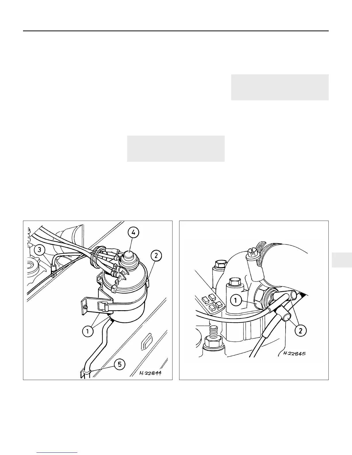
6.13 Charcoal canister fitted to carburettor models with
catalytic converter
1 Charcoal canister and
mounting bracket
2 Rubber retaining strap
3 Fuel return pipe connection
4 Purge valve vacuum
diaphragm
5 Vent hose
6.23 Thermostatic vacuum valve connections
1 Vacuum valve 2 Vacuum hoses
 Loading...