4 Inspect the canister. If it is cracked or
damaged, renew it. Look for fuel leaking from
the bottom of the canister. If fuel is leaking,
renew the canister, and check the hoses and
hose routing.
5 Checking of the thermostatic vacuum valve
and purge control valve should be entrusted
to a Rover dealer.
Component renewal
Charcoal canister - carburettor models
6 Disconnect the battery negative lead.
7 Remove the air cleaner assembly as
described in Part A of this Chapter.
8 Release the fasteners and detach the
ignition cover from the front of the engine.
9 Release the retaining clips, and disconnect
the charcoal canister hoses from the side of the
carburettor and from the breather hose T-piece.
10 Disconnect the charcoal canister vacuum
supply pipe from the thermostatic vacuum
switch situated on the thermostat housing.
11 Release the clip and disconnect the
canister hose from the fuel return pipe.
12 Chock the rear wheels then jack up the
front of the car and support it on axle stands
(see “Jacking and vehicle support”).
13 Working from underneath the left-hand
wing, release the rubber retaining strap, and
free the canister from its mounting bracket
(see illustration). Disconnect the vacuum
pipe from the purge valve diaphragm, then
release the canister vent hose from the wing
valance and withdraw the canister from
underneath the wing.
14 Refitting is the reverse sequence to
removal, noting that if a new canister is being
installed, it will be necessary to remove the
vent hoses from the original canister and
install them on the new one before fitting the
canister to the car. Ensure that all hoses are
correctly reconnected, and where necessary
securely held by their retaining clips.
Charcoal canister - fuel injection
models
15 Disconnect the battery negative lead.
16 Working in the engine compartment,
release the retaining clip(s), and disconnect
the canister hoses from the purge valve and
fuel hose.
17 Chock the rear wheels then jack up the
front of the car and support it on axle stands
(see “Jacking and vehicle support”).
18 From underneath the left-hand wheel
arch, release the air inlet duct, and position it
clear of the charcoal canister.
19 Release the canister vent hose from its
retaining clips, then release the rubber retaining
strap and remove the canister and hose
assembly from underneath the wheel arch.
20 Refitting is the reverse sequence to
removal, noting that if a new canister is being
installed, it will be necessary to remove the
vent hoses from the original canister and
install them on the new one before fitting the
canister to the car. Ensure that all hoses are
correctly reconnected, and where necessary
securely held by their retaining clips.
Thermostatic vacuum valve -
carburettor models
21 When the engine and radiator are cold,
either drain the cooling system as described
in Chapter 1, or unscrew the radiator filler cap
to release any remaining pressure, and have
ready a suitable plug that can be used
temporarily to stop the escape of coolant
while the switch is removed. If the latter
method is used, take care not to damage the
threads, and do not use anything which will
leave foreign matter inside the cooling
system.
22 Release the fasteners and remove the
ignition cover from the front of the engine.
23 Disconnect the vacuum hoses from the
thermostatic vacuum valve, which is screwed
into the front of the thermostat housing (see
illustration).
24 Slacken the radiator top hose retaining
clip, and slide the clip along the hose.
Unscrew the valve from the front of the
thermostat housing, and remove it along with
its sealing washer. Where necessary, plug the
housing aperture to minimise coolant loss.
25 On refitting, apply a smear of suitable
sealant to the valve threads, then refit the
valve and sealing washer to the thermostat
housing, tightening it to the specified torque.
Slide the radiator hose retaining clip back into
position, and tighten it securely.
26 Reconnect the vacuum hoses to the
valve, noting that the hose from the
carburettor must be connected to the union of
the valve marked “CARB”.
27 Refit the ignition cover, and refill or top-up
the cooling system as described in Chapter 1
or “Weekly Checks”.
Purge control valve - fuel injection
models
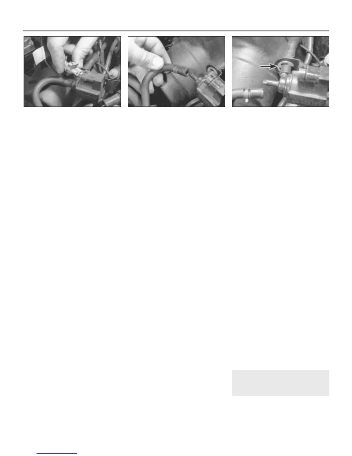
28 Disconnect the battery negative lead, then
disconnect the wiring connector from the
purge control valve (see illustration).
29 Release the retaining clips, and
disconnect the inlet and outlet hoses from the
valve (see illustration).
30 Prise out the C-clip which secures the
inlet hose adapter to the mounting bracket
(see illustration), then withdraw the adapter,
noting the O-ring which is fitted between the
adapter and purge valve. Discard the O-ring; it
must be renewed as a matter of course.
31 Slide the purge valve out of its mounting
bracket, and remove the valve from the car.
32 Refitting is the reverse sequence to
removal, using a new inlet hose adapter O-
ring.
Fuel tank breather two-way valve -
fuel injection models
33 Remove the fuel tank as described in Part
B of this Chapter.
34 Release the retaining clip, and disconnect
the two-way breather valve vent hose from
the fuel tank. Unclip the valve and hose
assembly from the tank seam, and remove it.
35 Release the retaining clips, disconnect the
hose from the valve, then undo the two
retaining nuts, and separate the valve from the
mounting bracket.
36 Refitting is the reverse sequence to
removal, tightening the valve retaining nuts to
the specified torque, and ensuring that the
hoses are securely reconnected.
7 Exhaust emission control
system - checking and
component renewal
2
Note: The following procedures apply to
those models without a catalytic converter.
Checking
4C•6 Exhaust and emission control systems
6.28 Disconnecting the purge valve wiring
connector
6.29 Release the retaining clip, and
disconnect the outlet hose from the purge
valve
6.30 Prise off the C-clip (arrowed), and
remove the inlet hose adapter from the
purge valve
 Loading...