1 Checking of the system as a whole entails a
close visual inspection of all hoses, pipes and
connections for condition and security.
Ensure also that the air pump drivebelt is in
satisfactory condition and correctly tensioned
as described in Chapter 1.
Air pump and air manifold
2 Check the condition of the air pump bearings
with the drivebelt removed by moving the pulley
from side to side. Any appreciable movement
indicates wear and will usually be accompanied
by excessive noise from the unit when in
operation. Apart from this, any known or
suspected faults on either of these components
should be attended to by a Rover dealer.
Check valve
3 Remove the valve as described later in this
Section and test it by gently blowing into each
end in turn. Air should pass through the valve
from the air supply end only. If air will pass in
both directions the valve is faulty and must be
renewed. Do not use high pressure air or air
from a tyre pump for this check or the valve
will be damaged.
Vacuum operated diverter valve
4 To test the operation of the valve, slacken
the hose clip and detach the diverter valve-to-
check valve hose at the check valve end.
5 Start the engine and allow it to idle. Air
pressure should be felt at the end of the
disconnected hose.
6 Operate the choke control, and air pressure
at the disconnected hose should be cut off
completely. If air can still be felt at the end of
the hose, the diverter valve is faulty and
should be renewed.
Cable operated diverter valve
7 The procedure for testing the cable
operated diverter valve is the same as for the
vacuum type described previously. If the valve
does not completely restrict the flow of air
when the choke control is operated, make
sure that the cable is correctly adjusted as
described later in this Section and then carry
out the test again. If the airflow is still not
completely restricted, renew the valve.
Gulp valve
8 This component can only be tested
satisfactorily using vacuum gauges. If the
valve is suspect it is recommended that the
testing is carried out by a Rover dealer.
Component renewal
Air pump
9 Remove the air pump drivebelt as
described in Chapter 1.
10 Slacken the clips and detach the outlet
hoses from the pump adapter.
11 Detach the HT lead and undo and remove
No 1 cylinder spark plug.
12 Slacken the bolt securing the pump
adjusting arm to the alternator pivot bolt.
13 Undo and remove the bolt securing the
adjusting arm to the air pump.
14 Undo and remove the air pump pivot nut
and bolt and lift off the pump.
15 Refitting is the reverse sequence to
removal. Ensure that the drivebelt is correctly
tensioned as described in Chapter 1.
Air manifold
16 Release the three retaining lugs and
remove the engine ignition shield, if fitted.
17 Detach the HT lead from No 1 cylinder
spark plug.
18 Undo and remove the four air manifold
unions from the cylinder head (see
illustration).
19 Slacken the clip securing the check valve
hose and lift away the air manifold complete
with check valve.
20 Hold the air manifold union with a spanner
and unscrew the check valve.
21 Refitting is the reverse sequence to
removal.
Check valve
22 Slacken the retaining clip and detach the
hose from the check valve.
23 Hold the air manifold union to prevent it
twisting and unscrew the check valve.
24 Refitting the check valve is the reverse
sequence to removal.
Vacuum operated diverter valve
25 Slacken all the hose clips and detach the
three air hoses and the small vacuum hose
from the valve body.
26 Undo and remove the two retaining nuts
and bolts and lift the valve off its mounting
bracket.
27 Refitting is the reverse sequence to
removal.
Cable operated diverter valve
28 Slacken the cable retaining screw and
slide the cable and retainer out of the valve
operating lever.
29 Slacken the hose clips and detach the
three hoses from the valve body, then lift the
valve off the engine.
30 Refitting the valve is the reverse sequence
Exhaust and emission control systems 4C•7
4C
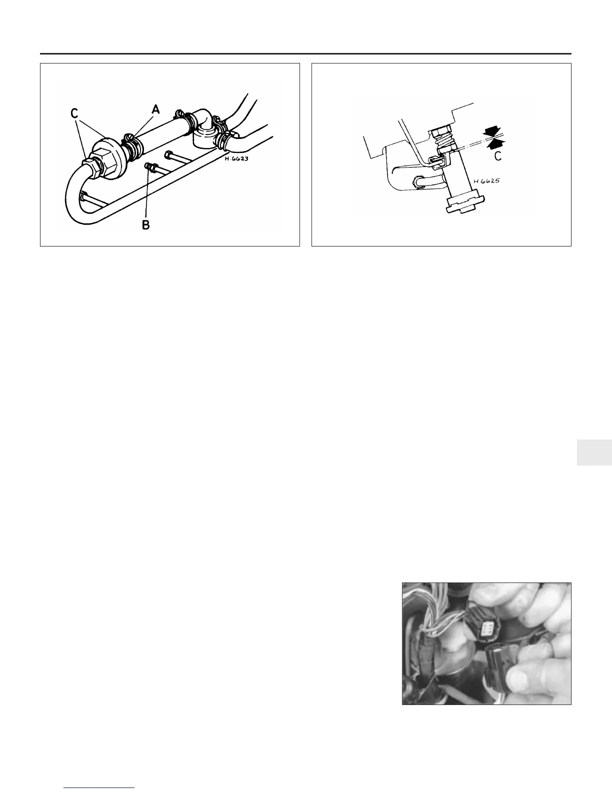
7.18 Air manifold assembly fitted to early models without
catalytic converter
A Check valve hose clip
B Air manifold unions
C Check valve and union
nut
7.32 Correct position of jet assembly when testing diverter valve
operation
C = 0.25 to 0.38 mm
8.4 Disconnecting the exhaust system
Lambda sensor wiring connector
 Loading...