regulator and cut-out in the control box
should be checked, and if necessary adjusted
as follows.
Voltage regulator adjustment
2 Check the regulator settings by removing
the leads A and A1 from the control box and
joining them together using a short length of
wire (see illustration). Connect the positive
clip of a 0 to 20 volt voltmeter to the D
terminal of the control box, and the negative
clip to a good earth.
3 Start the engine and slowly increase its
speed until the voltmeter needle flicks and
then steadies. This should occur at about
2000 rpm.
4 If the voltage at which the needle steadies
is outside the limits listed in the table, switch
off the engine, remove the control box cover
and turn the regulator adjusting screw a
fraction of a turn at a time, clockwise to
increase the setting and anti-clockwise to
decrease it (see illustration). Recheck the
voltage reading after each adjustment.
Air temperature Open circuit voltage
10ºC (50ºF) 16.1 to 16.7
20ºC (68ºF) 16.0 to 16.6
30ºC (86ºF) 15.9 to 16.5
40ºC (104ºF) 15.8 to 16.4
It is essential that the adjustments be
completed within 30 seconds of starting the
engine otherwise the heat from the shunt coil
will affect the readings.
Cut-out adjustment
5 With the control box A and A1 leads joined
together, and the voltmeter connected as
described in paragraph 2, the cut-in voltage
can be checked, and if necessary adjusted, as
follows.
6 Switch on the headlights to provide an
electrical load, start the engine and slowly
increase its speed. The voltage reading will
rise steadily, drop back and then rise again.
The point reached just before the drop back
should be between 12.7 and 13.3 volts.
7 If the reading obtained is outside these
limits, switch off the engine and turn the cut-
out adjusting screw a fraction of a turn at a
time clockwise to raise the voltage and anti-
clockwise to lower it (see illustration).
Recheck the voltage reading after each
adjustment. As with the voltage regulator, it is
essential that the adjustments be completed
within 30 seconds of starting the engine,
otherwise the heat from the shunt coil will
affect the readings.
8 After completing the adjustments remove
the voltmeter, disconnect the control box
leads and refit the cover.
Starting and charging systems 5A•5
5A
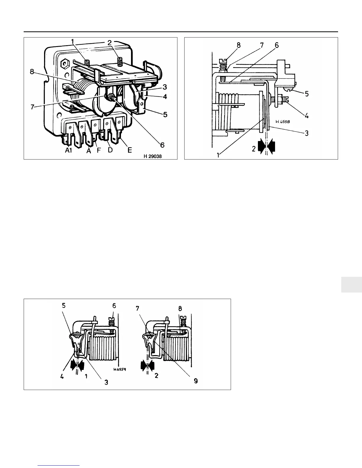
8.2 Control box components
1 Voltage adjusting screw
2 Cut-out adjusting screw
3 Fixed contact blade
4 Stop arm
5 Armature tongue and moving
contact
6 Regulator fixed contact screw
7 Regulator moving contact
8 Regulator series windings
8.4 Mechanical setting of regulator
1 Core face and shim
2 0.533 mm
3 Armature
4 Fixed contact adjustment
screw
5 Armature securing screws
6 Armature tension spring
7 Locknut
8 Voltage adjusting screw
8.7 Mechanical setting of cut-out
1 0.25 to 0.51 mm
2 0.76 mm
3 Follow through - 0.25 to 0.51 mm
4 Armature tongue and moving contact
5 Stop arm
6 Output adjusting screw
7 Armature securing screw
8 Armature tension spring
9 Fixed contact blade
 Loading...