19 As a double-check, remove the module,
gasket and connector, and lightly squeeze
together the terminals inside the connector.
Clean the terminals in the module and
distributor before refitting the module, and
remember to apply heat-conducting silicone
grease to the mounting face on the distributor.
20 Disconnect the wiring from the module,
clean the terminals, and lightly squeeze
together the terminals inside the connector
before refitting it. Make sure that the
connector is fully located over the base.
21 Check that the LT leads are correctly
fitted to the ignition coil.
4 Ignition system (fuel
injection models) - testing
2
1 If a fault appears in the engine management
(fuel injection/ignition) system first ensure that
the fault is not due to a poor electrical
connection or poor maintenance; ie, check
that the air cleaner filter element is clean, the
spark plugs are in good condition and
correctly gapped, that the engine breather
hoses are clear and undamaged, referring to
Chapter 1 for further information. Also check
that the accelerator cable is correctly adjusted
as described in Chapter 4B. If the engine is
running very roughly, check the valve
clearances and compression pressures as
described in Chapter 1 and 2A.
2 The only ignition system checks which can
be carried out by the home mechanic are
those described in Chapter 1, relating to the
spark plugs, HT leads, rotor arm and
distributor cap, and the ignition coil test
described in Section 10 of this Chapter.
3 If these checks fail to reveal the cause of
the problem the vehicle should be taken to a
suitably equipped Rover dealer for testing. A
wiring block connector is incorporated in the
engine management circuit into which a
special electronic diagnostic tester can be
plugged. The tester will locate the fault quickly
and simply alleviating the need to test all the
system components individually which is a
time consuming operation that carries a high
risk of damaging the ECU.
5 Contact breaker points -
adjustment
3
1 If an ignition shield is fitted over the front of
the engine, release the three plastic retaining
lugs and lift away the shield. Detach the two
spring clips or undo the two screws securing
the distributor cap to the distributor body and
lift off the cap (see illustration).
2 On models that have a distributor shield
attached to the inner front panel, remove the
ignition coil HT lead from the centre of the
distributor cap. Now detach the two
distributor cap securing spring clips or
screws. With careful manipulation it should be
possible to withdraw the distributor cap
upwards through the small space between the
rotor arm and the distributor shield. If difficulty
is experienced, undo and remove the
retaining screws and lift out the shield.
3 With the distributor cap removed, clean and
inspect it thoroughly as described in Chapter 1.
4 Gently prise the contact breaker points
open to examine the condition of their faces. If
they are rough and pitted or dirty, they should
be renewed. Disregard any blue discoloration
which may be apparent on their faces. This is
due to the formation of tungsten oxide; it has
no detrimental effect on ignition performance
nor is it indicative of condenser failure.
5 Assuming that the points are in a
satisfactory condition, or that they have been
renewed, the gap between the two faces
should be measured using feeler blades. Note
however that on later models no contact
breaker points gap is quoted by the
manufacturers. On these models, the gap can
only be adjusted using the dwell angle
method described from paragraph 10 onward.
6 To adjust the gap using feeler blades, turn
the engine over until the heel of the contact
breaker arm is on the peak of one of the four
cam lobes. On manual transmission models,
the engine can be turned over quite easily by
engaging top gear and moving the car
backwards or forwards until the points are
fully open. This should only be done on level
ground; and make sure that the car cannot
run away! An alternative method, and the
method that should be used on automatic
transmission models, is to press the fan belt
midway between the water pump pulley and
dynamo or alternator pulley and then turn the
fan blades. With the points fully open, a feeler
blade equal to the contact breaker points gap,
as stated in the Specifications, should now
just fit between the contact faces (see
illustrations).
Ignition system 5B•7
5B
5.1 Removing the distributor cap
5.6a Contact breaker points adjustment -
Lucas 25D4 distributor
1 Screwdriver slot for adjustment
2 Contact plate securing screw
3 Contact breaker points
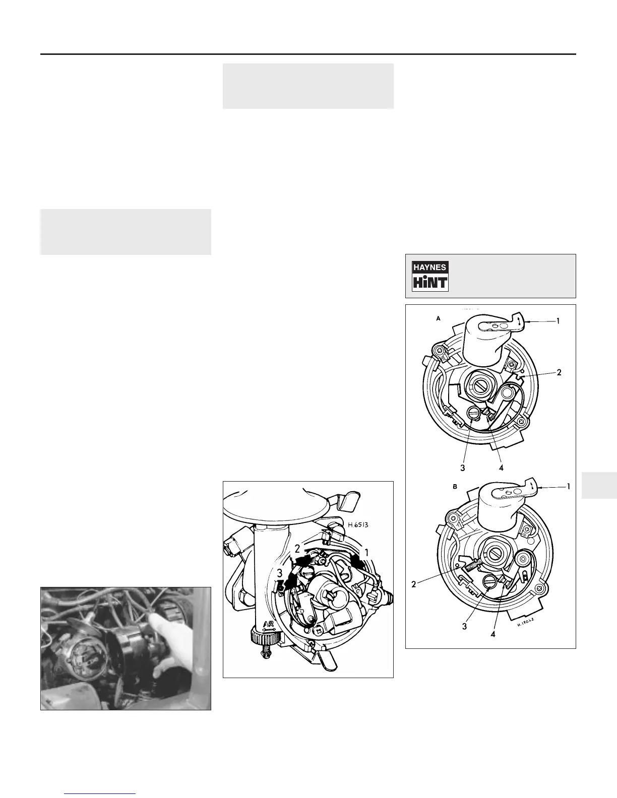
5.6b Contact breaker points adjustment -
Lucas 45D4 and 59D4 distributor
A Non-sliding contact type
B Sliding contact type
1 Rotor arm
2 Screwdriver slot for adjustment
3 Contact plate securing screw
4 Contact breaker points
Turning the engine will be
easier if the spark plugs are
removed first - see Chapter 1.
 Loading...