7 If the gap is too large or too small, slacken
the contact breaker securing screw slightly
using a short screwdriver. Now insert the
screwdriver into the slot on the side or at the
rear of the contact breaker plate and move the
plate in the desired direction to increase or
decrease the gap (see illustration).
8 Tighten the securing screw and recheck the
gap.
9 With the points correctly adjusted, refit the
distributor cap and ignition shield or
distributor shield if previously removed.
10 If a dwell meter is available, a far more
accurate method of setting the contact
breaker points gap is by measuring and
setting the distributor dwell angle.
11 The dwell angle is the number of degrees
of distributor cam rotation during which the
contact breaker points are closed, ie the
period from when the points close after being
opened by one cam lobe until they are
opened again by the next cam lobe. The
advantages of setting the points by this
method are that any wear of the distributor
shaft or cam lobes is taken into account, and
also the inaccuracies of using a feeler blade
are eliminated. In general, a dwell meter
should be used in accordance with the
manufacturer’s instructions. However, the use
of one type of meter is outlined as follows.
12 To set the dwell angle, remove the
distributor cap and rotor arm, and connect
one lead of the dwell meter to the + terminal
on the coil, and the other lead to the - coil
terminal.
13 Whilst an assistant turns on the ignition
and operates the starter, observe the reading
on the dwell meter scale. With the engine
turning over on the starter, the reading should
be as stated in the Specifications. Note:
Fluctuation of the dwell meter needle
indicates that the engine is not turning over
fast enough to give a steady reading. If this is
the case, remove the spark plugs and repeat
the checks.
14 If the dwell angle is too small, the contact
breaker point gap is too wide, and if the dwell
angle is excessive, the gap is too small.
15 Adjust the contact breaker points gap,
while the engine is cranking using the method
described in paragraph 7, until the correct
dwell angle is obtained.
16 When the dwell angle is satisfactory,
disconnect the meter and refit the rotor arm,
distributor cap and ignition or distributor
shield.
6 Contact breaker points -
renewal
3
Note: Carburettor models without electronic
ignition may be fitted with either a Lucas
23D4, 25D4, 45D4, 59D4 or Ducellier
distributor. Identify the unit being worked on
by referring to the illustrations and then
proceed as described below according to
distributor type.
Lucas 23D4 and 25D4
1 Remove the distributor cap as described in
the previous Section then withdraw the rotor
arm from the distributor spindle.
2 Undo and remove the small terminal nut,
together with the washer under its head, if
fitted. Lift off the flanged nylon insulator, the
condenser lead, and the low tension lead from
the terminal post.
3 Using a short screwdriver, unscrew the
single screw securing the adjustable contact
breaker plate to the distributor baseplate. Lift
off the screw and flat washer, taking care not
to drop them inside the distributor. The
contact breaker points can now be withdrawn.
4 To refit the points, first position the
adjustable contact breaker plate and secure it
with the retaining screw and washer. Fit the
fibre washer to the terminal post (and pivot
post where applicable), and then place the
contact breaker arm over it. Insert the flanged
nylon insulator with the condenser lead
immediately under its head, and the low
tension lead under that, over the terminal
post. Place the washer over the terminal post
and finally the retaining nut.
5 If a one-piece contact breaker point
assembly is being refitted, position the
contact assembly on the distributor baseplate
and refit the retaining screw and washer.
6 Place the condenser lead and low tension
lead under the head of the upper nylon
insulator, and then fit the insulator to the
terminal post. Finally refit the washer and
retaining nut.
7 The contact breaker points gap should now
be adjusted as described in the previous
Section.
Lucas 45D4 and 59D4
8 Remove the distributor cap as described in
the previous Section then withdraw the rotor
arm from the distributor spindle (see
illustration).
5B•8 Ignition system
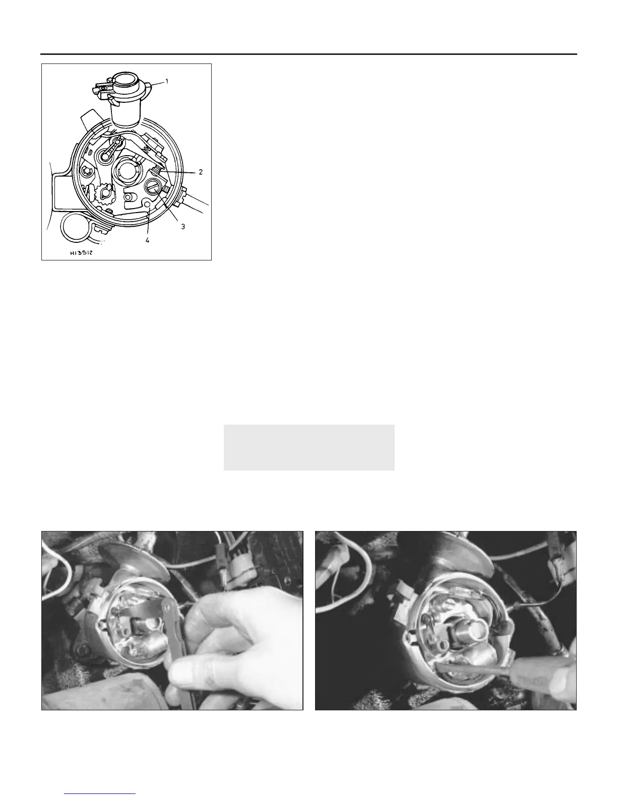
5.6c Contact breaker points adjustment -
Ducellier distributor
1 Rotor arm
2 Contact breaker points
3 Contact plate securing screw
4 Screwdriver slot for adjustment
5.6d Using feeler blades to check the contact breaker points gap 5.7 Adjusting the contact breaker points
 Loading...