Refitting
11 Ensure that the crankshaft is still positioned
so that number 1 cylinder is at TDC on its
compression stroke, then refit the distributor to
the engine, aligning the drive dog with the slot in
the drive. When inserting the distributor into the
engine aperture, press down lightly on the
distributor body and at the same time rotate the
distributor shaft slightly. When the lug on the
distributor drive dog engages with the slot on
the driveshaft, the distributor will move in
toward the engine a further 6.3 mm.
12 If the original distributor is being refitted,
align the marks made on removal between the
distributor body and clamp plate. If a new
distributor is being fitted to carburettor models,
turn the distributor body until the rotor arm is
pointing toward the No 1 HT lead segment in
the distributor cap. If a new distributor is being
fitted to fuel injection models, turn the
distributor body until the rotor arm and body
are aligned as shown (see illustration).
13 With the distributor correctly positioned,
tighten the pinch bolt and clamp plate bolt or
refit the C-shaped plate and tighten the bolt.
14 Refit the cap to the distributor, and secure
with the clips or retaining screws.
15 If removed, refit the rocker cover and
reconnect any disturbed spark plug HT leads.
16 On carburettor models, reconnect the
distributor wiring and vacuum advance pipe.
17 Before refitting the remainder of the
components on carburettor models, the
ignition timing must be checked and adjusted
as described in Section 13.
9 Distributor - dismantling,
inspection and reassembly
3
Note: The following procedures are applicable
to the distributors fitted to carburettor models.
The distributor fitted to fuel injection models
consists simply of a shaft and housing and
cannot be dismantled. Check the cost and
availability of replacement parts before
proceeding. If the distributor is excessively
worn it may be beneficial (or necessary) to
obtain a reconditioned unit.
Dismantling
Lucas 23D4 and 25D4
1 Remove the distributor from the car as
described in Section 8.
2 Withdraw the rotor arm from the distributor
spindle and then remove the contact breaker
points as described in Section 6.
3 Undo and remove the single retaining
screw and lift off the condenser (see
illustration).
4 Unhook the vacuum unit operating spring
from the post on the distributor baseplate (not
23D4).
5 Undo and remove the two small screws and
spring washers which secure the baseplate to
the distributor body. Note that one of these
screws also retains the baseplate earth lead.
6 Now carefully lift out the baseplate.
7 Make a note of the position of the rotor arm
drive slot, in the spindle, in relation to the
offset driving dog at the opposite end of the
distributor. It is essential that this is
reassembled correctly, otherwise the ignition
timing will be 180º out.
8 Undo and remove the cam spindle retaining
screw which is located in the centre of the
rotor arm drive.
9 Remove the two centrifugal advance weight
tension springs and then lift off the cam
spindle. It is quite likely that the cam spindle
will prove difficult to remove and will not slide
readily off the shaft. If this is the case, apply
liberal amounts of penetrating oil to the top of
the spindle and rotate it back and forth while
at the same time pulling upward. This should
free the spindle and allow it to be removed
from the shaft.
Ignition system 5B•11
5B
8.12 Correct distributor rotor arm offset
and body position (No 1 cylinder at
TDC on compression stroke) -
fuel-injected models
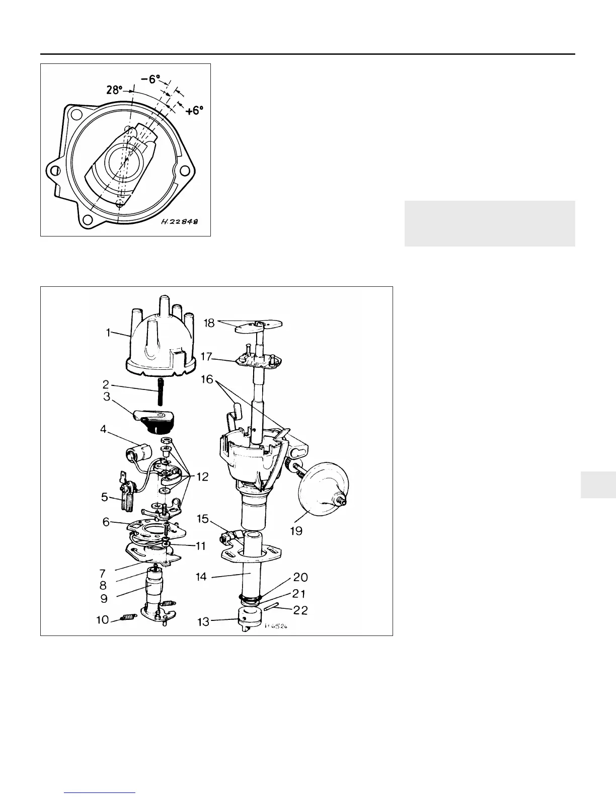
9.3 Exploded view of Lucas 25D4 distributor
1 Distributor cap
2 Brush and spring
3 Rotor arm
4 Condenser
5 Terminal and lead
6 Moving baseplate
7 Fixed baseplate
8 Cam screw
9 Cam
10 Advance spring
11 Earth lead
12 Contact breaker points
13 Driving dog
14 Bush
15 Clamp plate
16 Cap retaining clips
17 Shaft and action plate
18 Bob weights
19 Vacuum unit
20 O-ring oil seal
21 Thrust washer
22 Taper pin
 Loading...