12 Reluctor ring (fuel injection
models) - removal and
refitting
3
Manual transmission models
Removal
1 Remove the flywheel as described in
Chapter 2A.
2 Slacken and remove the two retaining
screws, and remove the reluctor ring from the
rear of the flywheel.
3 Check the ring for obvious signs of wear or
damage, and renew it if necessary.
Refitting
4 Refitting is the reverse sequence to
removal, ensuring that the reluctor retaining
screws are securely tightened.
Automatic transmission models
5 On automatic transmission models, the
reluctor ring is an integral part of the torque
converter assembly, and is not available
separately. Refer to Chapter 2A for
information on torque converter removal and
refitting. If the reluctor ring is damaged, the
completed torque converter assembly must
be renewed.
13 Ignition timing - checking and
adjustment
3
Carburettor models
1 In order that the engine can run efficiently, it
is necessary for a spark to occur at the spark
plug and ignite the fuel/air mixture at the
instant just before the piston, on the
compression stroke reached the top of its
travel. The precise instant at which the spark
occurs is determined by the ignition timing,
and this is quoted in degrees before top dead
centre (BTDC). On pre-1976 models the
ignition timing may be checked with the
engine stationary (this is the static ignition
timing), or more accurately with the engine
running, using a stroboscopic timing light. On
post-1976 models a stroboscopic timing light
must be used, as no static values are quoted
by the manufacturer.
2 If the distributor has been dismantled or
renewed, or if its position on the engine has
been altered, it will be necessary to reset the
ignition timing using the following procedure.
3 First ensure that the contact breaker points
are in good condition and that the gap is
correctly set as described in Section 5.
4 To obtain the static timing setting, remove
the distributor cap and place it to one side.
Gain access to the ignition timing marks by
undoing the two bolts securing the inspection
plate to the top of the flywheel housing and
lifting off the plate. On models fitted with
automatic transmission, withdraw the rubber
grommet from the top of the converter
housing. On later models there is a timing
scale on the timing cover, together with a
notch or pointer on the crankshaft pulley.
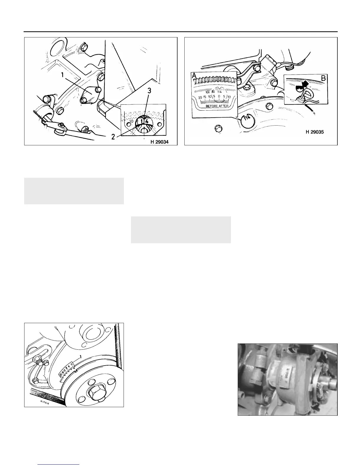
5 The timing marks on the flywheel (or torque
converter), and the pointer on the housing,
can be viewed through the inspection
aperture using a small mirror. The 1/4 mark on
the flywheel or torque converter indicates
TDC, and the 5, 10 and 15 marks indicate 5º,
10º, and 15º of advance before TDC
respectively. On later models with a timing
scale on the timing cover, each pointer on the
scale represents 4º of ignition advance, with
the larger pointer indicating TDC (see
illustrations).
6 Refer to the Specifications at the beginning
of this Chapter for the correct ignition timing
static setting. The distributor number will be
found stamped on the side of the distributor
body, usually just below the vacuum unit (see
illustration).
7 Having determined the correct setting, turn
the engine over until No 1 piston is
approaching TDC on the compression stroke.
This can be checked by removing No 1 spark
plug and feeling the pressure being developed
in the cylinder as the piston rises, or by
5B•16 Ignition system
13.5c The timing scale located on the
timing cover of later models
1 Timing scale
13.6 The distributor number is stamped on
the body below the vacuum unit
13.5a Ignition timing marks - manual transmission models
1 Inspection cover 2 Timing marks 3 Pointer
13.5b Location of timing marks on torque converter -
automatic transmission models
A Detail showing alternative
timing marks
B Insert screwdriver to turn
converter
 Loading...