60 Refit the contact breaker points as
described in Section 6, and then place the
rotor arm on the spindle.
61 The distributor can now be refitted to the
car as described in Section 8.
Lucas 65DM4
62 Refit the shaft assembly if removed,
locate the drive dog, and drive in the roll pin.
Check that the drive dog offset is positioned
correctly in relation to the rotor arm (see
illustration 9.22).
63 Lubricate the shaft bearing with a little
engine oil. Also lubricate the centrifugal
advance mechanism.
64 Locate the thrustwasher in the upper
housing.
65 Grease the end of the link arm, then insert
the vacuum unit in the upper housing, and
engage the stator pack with the link arm.
Retain the stator pack with the thrustwasher
and circlip, and fit the vacuum unit retaining
screw.
66 Insert the pick-up winding in the upper
housing, centralise the terminals in the
aperture, then fit the clamp ring with the cut-
out over the aperture.
67 Fit the lower housing to the upper
housing, and insert the screws finger-tight.
Rotate the shaft several times, then fully
tighten the screws.
68 Check that the reluctor arms do not touch
the stator pack arms, as they can easily be
bent inadvertently.
69 Fit the connector and gasket.
70 Apply heat-conducting silicone grease to
the mounting face of the amplifier module,
then fit the module and tighten the screws.
Refit the rotor arm.
71 If necessary, renew the O-ring on the
shank of the distributor, then refit the
distributor, as described in Section 8.
Ducellier
72 Lubricate the centrifugal advance weight
pivot posts and the distributor cam sparingly
with general purpose grease.
73 Position the baseplate in the distributor
body, making sure that the nylon pressure
pad and spring are in place, with the pad in
contact with the distributor shaft.
74 Refit the distributor cap retaining clip,
located opposite to the vacuum unit, and
secure with the retaining screw.
75 Position the operating link of the vacuum
unit together with the eccentric cam, over the
baseplate D-post. Turn the eccentric cam so
that it is in the same position relative to the
spring seat of the operating link, as marked
during dismantling. Now carefully refit the
small retaining circlip.
76 Secure the vacuum unit, condenser, and
the remaining distributor cap retaining clip to
the distributor body, using the two screws.
77 Refit the contact breaker points as
described in Section 6, and then place the
rotor arm on the spindle.
78 The distributor can now be refitted to the
car as described in Section 8.
10 Ignition coil - removal, testing
and refitting
2
Removal
1 Release the fasteners, and remove the
ignition shield from the front of the engine.
2 Where applicable, slide back the rubber
cover fitted over the end of the coil to expose
the wiring connectors. Disconnect the LT
wiring from the coil terminals, noting their
positions. Disconnect the HT lead from the
centre of the coil.
3 If the coil is mounted on the dynamo, undo
and remove the mounting bracket retaining
bolts and lift off the coil. Slacken the clamp
bolt and slide the coil out of its mounting
bracket.
4 If the coil is mounted on the cylinder head,
slacken and remove the nut securing the coil
to the cylinder head stud, and remove the coil
and bracket assembly from the engine. If
necessary disconnect the suppressor, then
slacken the clamp bolt and slide the coil out of
its mounting bracket.
Testing
5 Testing the coil consists of using a
multimeter set to its resistance function, to
check the primary (LT “+” to “-” terminals) and
secondary (LT “+” to HT lead terminal)
windings for continuity. If the meter is used,
the resistance of either winding can be
checked and compared with the specified
value; note that although no specified value is
given by Rover for the secondary windings, as
a guide, the reading should be in the region of
5 to 15 kohms. The resistance of the coil
windings will vary slightly according to the coil
temperature; those specified are accurate
only when the coil is at 20ºC.
6 Using an ohmmeter or continuity tester,
check that there is no continuity between the
HT lead terminal and the coil body.
7 If the coil is faulty, it must be renewed.
Ensure that the correct coil is obtained for the
type of ignition system fitted.
Refitting
8 Refitting is the reverse sequence to
removal, ensuring that the wiring connectors
are securely reconnected.
11 Crankshaft sensor (fuel
injection models) - removal
and refitting
1
Removal
Manual transmission models
1 Release the fasteners, and remove the
ignition cover from the front of the engine.
Disconnect the battery negative lead.
2 Chock the rear wheels then jack up the
front of the car and support it on axle stands
(see “Jacking and vehicle support”).
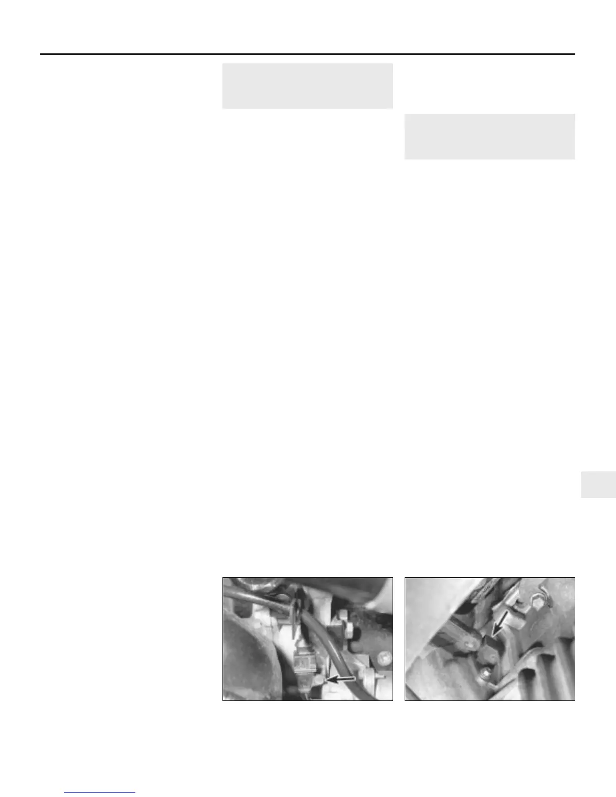
3 Remove the tie securing the crankshaft
sensor wiring to the starter motor solenoid,
and undo the bolt securing the wiring
connector to the mounting bracket (see
illustration).
4 Disconnect the sensor wiring connector,
then undo the bolts securing the sensor to the
flywheel housing, and remove the sensor from
the car (see illustration).
Automatic transmission models
5 Disconnect the battery negative lead, then
undo the two bolts securing the ECU
mounting bracket to the right-hand wing
valance, and position the ECU clear of the
crankshaft sensor.
6 Undo the bolt securing the wiring connector
to the mounting bracket, then disconnect the
sensor wiring connector.
7 Slacken and remove the two bolts securing
the sensor to the torque converter housing,
and remove the sensor from the car.
Refitting
8 On all models, refitting is the reverse
sequence to removal, tightening the sensor
mounting bolts to the specified torque.
Ignition system 5B•15
5B
11.3 Crankshaft sensor wiring connector
retaining bolt (arrowed) -
manual transmission models
11.4 Crankshaft sensor location (arrowed)
on manual transmission models -
viewed from underneath
 Loading...