1 General information
Drum brakes are fitted to the front and rear
wheels on all early models except Cooper S
and 1275 GT versions. These, and all later
models have disc brakes at the front. The
braking system is operated hydraulically by a
master cylinder, which is actuated by the
brake pedal. Disc brake models may also be
servo assisted by a vacuum servo unit
mounted in the engine compartment.
The hydraulic system on early models is of
the single circuit type, whereby both the front
and rear brakes are operated by the same
hydraulic system from the master cylinder. On
later models a dual circuit system is used,
whereby the brakes at each pair of wheels are
operated by a separate hydraulic system from a
tandem master cylinder. In the event of
hydraulic failure in one circuit, full braking force
will still be available at two wheels. On early
dual circuit systems a diagonal split is used,
each circuit supplying one front and one
diagonally opposite rear brake. Later versions
employ a front-to-rear split whereby both front
and both rear brakes are operated by a
separate hydraulic circuit. A pressure
differential warning actuator is fitted to certain
models to inform the driver of a hydraulic circuit
failure via an illuminated warning light, and also
to restrict the flow of hydraulic fluid into the
failed circuit. This unit is either mounted
separately on the engine compartment
bulkhead, or incorporated in the master
cylinder. On single circuit and certain dual
circuit systems, a pressure reducing valve is
incorporated in the rear brake circuit. This valve
reduces hydraulic fluid pressure to the rear
brakes and prevents rear wheel lock-up due to
forward weight transfer under heavy braking.
On models not equipped with a pressure
reducing valve, the same effect is achieved by
reducing the rear wheel cylinder piston
diameters. A low brake fluid warning light is also
fitted to later models operated by a float-type
switch in the master cylinder reservoir filler cap.
On models fitted with front drum brakes,
the brake shoes are operated by two single
piston wheel cylinders at each front wheel.
Models with front disc brakes utilise a twin
piston fixed type caliper at each front wheel.
At the rear on all models, one twin piston
wheel cylinder operates each wheel’s leading
and trailing brake shoes.
The handbrake provides an independent
mechanical means of rear brake shoe
application.
Adjustment of the drum brakes is provided
by two adjusters on each front brake and a
single adjuster on each rear brake. Periodic
adjustment is necessary to compensate for
wear on the brake shoe friction linings. The
front disc brakes do not require adjustment,
as the pistons in the caliper automatically
compensate for brake pad wear.
Note: When servicing any part of the system,
work carefully and methodically; also observe
scrupulous cleanliness when overhauling any
part of the hydraulic system. Always renew
components (in axle sets, where applicable) if
in doubt about their condition, and use only
genuine Rover replacement parts, or at least
those of known good quality. Note the
warnings given in “Safety first” and at relevant
points in this Chapter concerning the dangers
of asbestos dust and hydraulic fluid.
2 Hydraulic system - bleeding
3
Warning: Hydraulic fluid is
poisonous; wash off immediately
and thoroughly in the case of
skin contact, and seek
immediate medical advice if any fluid is
swallowed or gets into the eyes. Certain
types of hydraulic fluid are inflammable,
and may ignite when allowed into contact
with hot components; when servicing any
hydraulic system, it is safest to assume that
the fluid IS inflammable, and to take
precautions against the risk of fire as
though it is petrol that is being handled.
Hydraulic fluid is also an effective paint
stripper, and will attack plastics; if any is
spilt, it should be washed off immediately,
using copious quantities of clean water.
Finally, it is hygroscopic (it absorbs
moisture from the air). The more moisture
is absorbed by the fluid, the lower its
boiling point becomes, leading to a
dangerous loss of braking under hard use.
Old fluid may be contaminated and unfit for
further use. When topping-up or renewing
the fluid, always use the recommended
type, and ensure that it comes from a
freshly-opened sealed container.
General
1 The correct functioning of the brake
hydraulic system is only possible after
removing all air from the components and
circuit; this is achieved by bleeding the system.
2 During the bleeding procedure, add only
clean, fresh hydraulic fluid of the specified
type; never re-use fluid that has already been
bled from the system. Ensure that sufficient
fluid is available before starting work.
3 If there is any possibility of incorrect fluid
being used in the system, the brake lines and
components must be completely flushed with
uncontaminated fluid and new seals fitted to
the components.
4 If brake fluid has been lost from the master
cylinder due to a leak in the system, ensure
that the cause is traced and rectified before
proceeding further.
5 Park the car on level ground, switch off the
ignition and select first gear (manual
transmission) or Park (automatic transmission)
then chock the wheels and release the
handbrake.
6 Check that all pipes and hoses are secure,
unions tight, and bleed screws closed.
Remove the dust caps and clean any dirt from
around the bleed screws.
7 Unscrew the master cylinder reservoir cap,
and top-up the reservoir. Refit the cap loosely,
and remember to keep the reservoir topped
up throughout the procedure, otherwise there
is a risk of further air entering the system.
8 There are a number of one-man, do-it-
yourself, brake bleeding kits currently
available from motor accessory shops. It is
recommended that one of these kits is used
wherever possible, as they greatly simplify the
bleeding operation, and also reduce the risk
of expelled air and fluid being drawn back into
the system. If such a kit is not available,
collect a clean glass jar of reasonable size and
a suitable length of plastic or rubber tubing,
which is a tight fit over the bleed screw.
9 If a kit is to be used, prepare the car as
described previously, and follow the kit
manufacturer’s instructions, as the procedure
may vary slightly according to the type being
used; generally, they are as outlined in the
text below.
10 The procedure for bleeding varies
according to whether the car is equipped with
a single or dual circuit braking system, and
also with dual circuit systems, the type of
master cylinder that is fitted. Identify the type
of system being worked on by referring to the
illustrations, and to Section 13, then proceed
according to type.
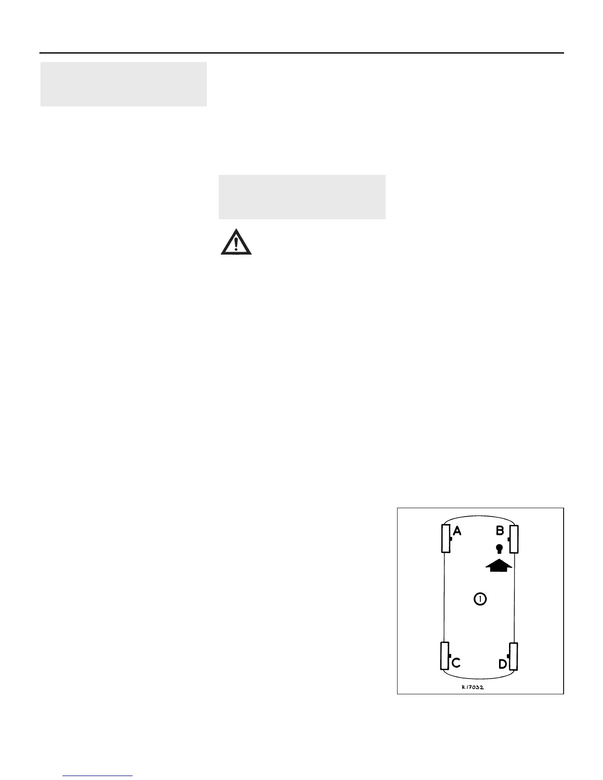
Single circuit system
11 To bleed the system, clean the area
around the bleed screw of the wheel to be
bled. If the hydraulic system has only been
partially disconnected, and suitable
precautions were taken to prevent further loss
of fluid, it should only be necessary to bleed
that part of the system. However, if the entire
system is to be bled, proceed in the sequence
ABCD for right-hand drive cars, and BADC for
left-hand drive vehicles (see illustration).
9•2 Braking system
2.11 Bleeding sequence for single circuit
braking systems
 Loading...