12 Remove the master cylinder reservoir filler
cap and top-up the reservoir. Periodically
check the fluid level during the bleeding
operation and top-up as necessary.
13 If a one-man brake bleeding kit is being
used, connect the outlet tube to the bleed
screw (see illustration) and then open the
screw approximately one turn. Position the
unit so that it can be viewed from the car then
depress the brake pedal to the floor and
rapidly release it. The one-way valve in the kit
will prevent expelled air from returning to the
system at the end of each stroke. Repeat this
operation until clean hydraulic fluid, free from
air bubbles, can be seen coming through the
tube. Then tighten the bleed screw and
remove the outlet tube.
14 If a one-man brake bleeding kit is not
available, connect one end of the plastic
tubing to the bleed screw and immerse the
other end in the jar containing sufficient clean
hydraulic fluid to keep the end of the tube
submerged.
15 Open the bleed screw approximately one
turn and have your assistant depress the
brake pedal to the floor, and then rapidly
release it. Tighten the bleed screw at the end
of each downstroke to prevent expelled air
from being drawn back into the system.
16 Repeat this operation until clean hydraulic
fluid, free from air bubbles, can be seen
coming through the tube. Then tighten the
bleed screw on a downstroke and remove the
plastic tube.
17 If the entire system is being bled the
procedures described previously should now
be repeated at each wheel in the correct
sequence.
18 When completed, check the fluid level in
the master cylinder, top-up if necessary, and
refit the cap. Check the feel of the brake
pedal, which should be firm and free from any
sponginess; this would indicate air still
present in the system.
19 Discard any used hydraulic fluid, as the
minute air bubbles and contamination which
will be present in the fluid make it unsuitable
for further use in the hydraulic system.
Dual circuit system (early type)
20 The following procedure is applicable to
the type 1 tandem master cylinder (see
Section 13) fitted to diagonally-split hydraulic
systems.
21 To bleed the system, clean the area
around the bleed screws of the wheels to be
bled. If only half of the hydraulic system has
been disconnected, it should only be
necessary to bleed that half, provided no air
has entered the other half. However, if the
entire system is to be bled, proceed in the
sequence ABCD for right-hand drive cars and
BADC for left-hand drive vehicles (see
illustration).
22 The procedure is now the same as
described in paragraphs 12 to 19 for the
single circuit system, except that the brake
pedal should be depressed rapidly, held down
for three seconds and then released slowly. A
delay of fifteen seconds should then be
allowed before repeating.
23 When bleeding Is complete, check the
operation of the pressure differential warning
actuator as described in Section 20.
Dual circuit system (later type)
24 The following procedure is applicable to
the type 2, 3 and 4 tandem master cylinders
(see Section 13) fitted to diagonally-split and
front-to-rear split hydraulic systems.
25 Before commencing the bleeding
operation, unscrew the brake failure warning
switch (where fitted) from the side of the
master cylinder body. (No fluid loss will occur
unless there is internal pressure differential
piston seal failure.)
Note: If the system is being bled following
renewal of the master cylinder, check whether
a plastic spacer is fitted between the pressure
switch and master cylinder body. If a spacer is
present, leave it in position during the
bleeding operation and then discard it.
26 To bleed the system, clean the area
around the bleed screws of the wheels to be
bled. If only half of the hydraulic system has
been disconnected, it should only be
necessary to bleed that half, provided no air
has entered the other half. However, if the
entire system is to be bled, it must be done in
the following sequence.
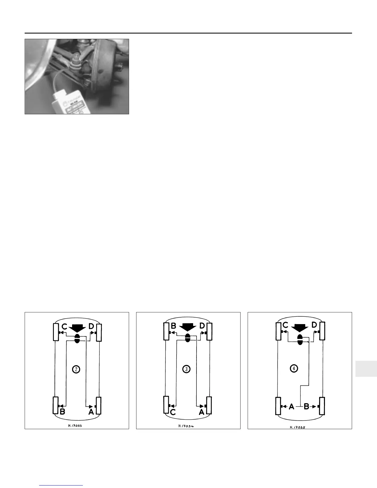
27 For diagonally split systems, proceed in
the order ABCD for right-hand drive cars, and
CDAB for left-hand drive vehicles (see
illustration).
28 For front-to-rear split systems, proceed in
the order ABCD, irrespective of driving
position (see illustration).
29 The procedure is now the same as
described in paragraphs 12 to 19 for the
single circuit system, except that the brake
pedal should be depressed rapidly, held down
for three seconds, and then released slowly. A
delay of fifteen seconds should then be
allowed before repeating.
30 Where applicable, refit the brake failure
warning switch and tighten it to the specified
torque after completing the bleeding
operation.
Braking system 9•3
9
2.13 One-man brake bleeding kit
connected to the front bleed screw
2.21 Bleeding sequence for type 1 tandem
master cylinder - see text
2.27 Bleeding sequence for type 2, 3 and 4
tandem master cylinders with diagonal
split dual circuit braking systems - see text
2.28 Bleeding sequence for type 2, 3 and 4
tandem master cylinders with front-to-rear
split dual circuit braking systems - see text
 Loading...