11 Disconnect the vacuum hose from the
servo unit, and release it from the clip.
12 Extract the split pin, and withdraw the
clevis pin securing the pushrod to the brake
pedal.
13 Disconnect the anti-run-on valve hoses,
and plug them.
14 Unscrew the bolt securing the anti-run-on
valve to the servo mounting bracket.
15 Unscrew the mounting nuts and bolts,
and withdraw the servo unit and bracket
assembly from the engine compartment.
16 Separate the servo unit from the bracket
by disconnecting the clevis and unscrewing
the nuts. Prise the O-ring from the recess in
the master cylinder.
17 Refitting is the reverse sequence to
removal. Smear the O-ring with clean brake
hydraulic fluid and bleed the hydraulic system
as described in Section 2 on completion.
22 Vacuum servo unit air filter
(1989 models onward) -
renewal
2
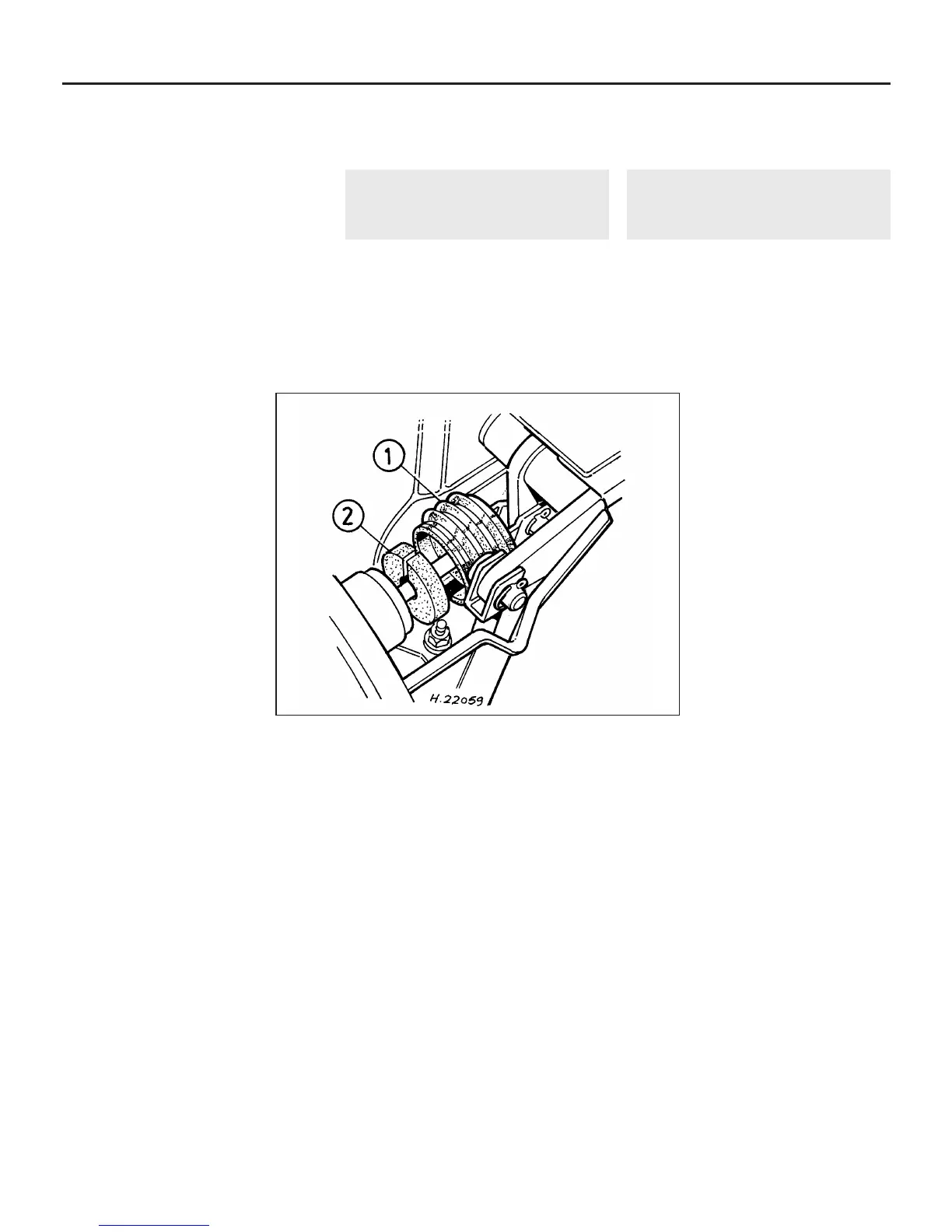
1 Working in the engine compartment, prise
back the rubber boot from the rear of the
servo, and slide it along the push rod (see
illustration).
2 Prise the air filter from inside the servo
body.
3 Cut the new air filter in one place with a
sharp knife, then locate it over the pushrod
and push it into the servo body.
4 Refit the rubber boot.
23 Brake pedal - removal and
refitting
1
The brake pedal is removed together with
the clutch pedal, and full information on the
removal and refitting procedure will be found
in Chapter 6.
9•18 Braking system
22.1 Vacuum servo unit air filter
1 Rubber boot 2 Air filter
 Loading...