3 Undo and remove the retaining bolt and lift
off the valve.
4 The pressure reducing valve is a sealed unit
and cannot be dismantled. If the valve is faulty
it must be renewed as a complete assembly.
Refitting
5 Refitting is the reverse sequence to
removal. Bleed the hydraulic system as
described in Section 2 on completion.
20 Pressure differential warning
actuator (dual circuit system)
- removal, overhaul and refitting
3
Note: On early type dual circuit braking
systems, a separate pressure differential
warning actuator, located on the engine
compartment bulkhead, informs the driver of
failure of one of the braking hydraulic circuits.
On later systems so equipped, the warning
actuator is incorporated in the master cylinder.
Before starting work, refer to the warning at
the beginning of Section 2 concerning the
dangers of hydraulic fluid.
Removal
1 Unscrew the brake master cylinder filler
cap, place a piece of polythene over the filler
neck and refit the cap. This will reduce
hydraulic fluid loss when the brake pipes are
disconnected.
2 Detach the electrical connector from the
switch on the side of the warning actuator
body.
3 Unscrew the hydraulic pipe unions and
carefully remove the pipes. Protect the
disconnected unions from possible dirt
ingress.
4 Undo and remove the retaining bolt and lift
off the unit.
Overhaul
5 Clean off the exterior of the unit and make
sure it is free from dirt and grit.
6 Undo and remove the end plug and discard
the copper washer (see illustration).
7 Unscrew the warning light switch.
8 Tap the warning actuator body on a block
of wood to release the shuttle valve piston
assembly and withdraw it from the bore.
9 Remove the two rubber seals from the
piston.
10 Wash the components in clean hydraulic
fluid or methylated spirit and dry with a lint-
free cloth.
11 Carefully inspect the piston and the
casing bore for scoring and damage. If the
bore and piston are not in perfect condition,
renew the complete pressure differential
warning actuator. If the components are in a
satisfactory condition obtain new seals and a
new copper sealing washer. Do not re-use the
old seals.
12 Reassembly of the unit is the reverse of
the dismantling sequence. Lubricate all the
parts with clean hydraulic fluid and assemble
them wet. Observe the specified torque
wrench settings when refitting the end plug
and warning light switch.
Refitting
13 Refitting is the reverse sequence to
removal. Bleed the hydraulic system as
described in Section 2 after refitting.
14 After bleeding the braking system, switch
on the ignition and observe the brake failure
warning light. If the light is illuminated, press
the brake pedal hard: the light should go out
and stay out when the pedal is released. If the
light fails to go out, the pressure in the braking
system is unbalanced or there is a fault in the
warning actuator or its switch. Bleed the
braking system again, and if this fails to cure
the trouble, investigate the warning actuator
and the switch.
15 If the brake failure warning light is not
illuminated when the brake pedal is
depressed, but does come on when the test-
push on the switch is operated, then the
system is functioning satisfactorily.
21 Vacuum servo unit - removal
and refitting
3
Pre-1989 models
Removal
1 Unscrew the brake master cylinder filler
cap, place a piece of polythene over the filler
neck and refit the cap. This will minimise
hydraulic fluid loss when the servo is
removed.
2 From under the right-hand front wing
detach the inlet ducting from the inlet unit and
then withdraw the inlet unit from inside the
engine compartment.
3 Disconnect the vacuum pipe from the one-
way valve on the servo unit.
4 Remove the securing bracket from the end
of the servo unit.
5 Unscrew the hydraulic pipe unions and
carefully withdraw them from the servo.
Protect the disconnected unions against
possible dirt ingress.
6 Undo and remove the nuts securing the
servo to its mounting bracket and lift away the
unit.
Refitting
7 Refitting is the reverse sequence to
removal. Bleed the hydraulic system as
described in Section 2 on completion.
1989 models onward
Removal
8 Disconnect the low brake fluid level warning
light wiring from the master cylinder fluid
reservoir filler cap.
9 Unscrew the master cylinder mounting nuts
from the servo unit.
10 Position a container beneath the master
cylinder, then loosen (but do not remove) the
hydraulic pipe union nuts, to prevent damage
to the pipes when the master cylinder is
moved from the servo unit. Move the master
cylinder clear of the servo unit, then retighten
the union nuts.
Braking system 9•17
9
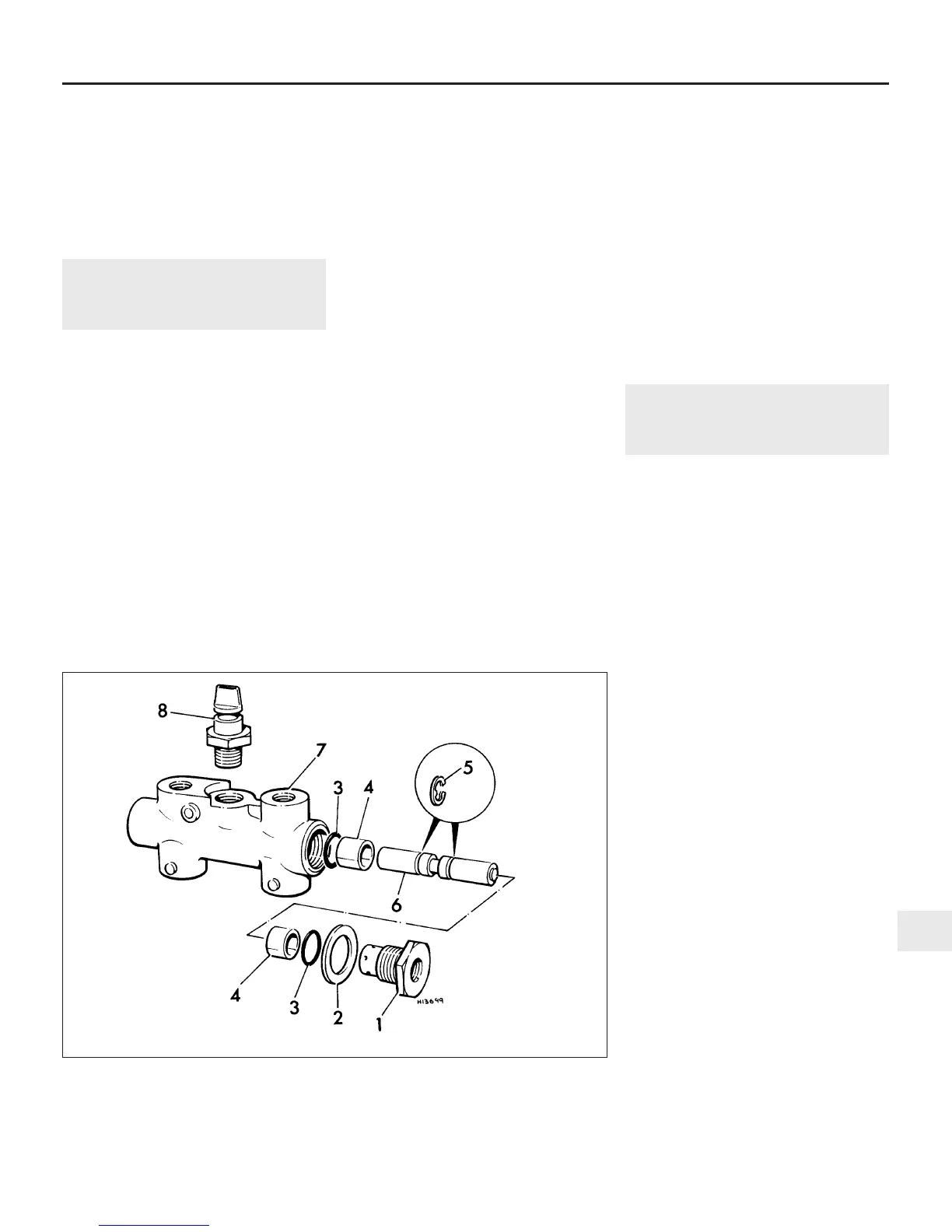
20.6 Exploded view of the pressure differential warning actuator
1 End adapter
2 Copper washer
3 O-ring
4 Sleeve
5 Circlip
6 Piston
7 Body
8 Switch
 Loading...