14 Note the position and direction of fitting of
the rubber seals on the piston assemblies,
then carefully remove them.
15 Wash all the parts in clean hydraulic fluid
or methylated spirit and dry with a lint-free
cloth.
16 Examine the bore of the master cylinder
carefully for any signs of scores or ridges. If
this is found to be smooth all over, new seals
can be fitted. If, however, there is any doubt
about the condition of the bore, then a new
cylinder must be obtained and fitted. Never
re-use old seals, as they will have deteriorated
with age even though this may not be evident
during visual inspection.
17 Reassembly of the master cylinder is the
reverse sequence to removal, but the
following additional points should be noted:
a) Thoroughly lubricate all components in
clean hydraulic fluid and assemble them
wet.
b) Refit the seals onto the pistons using
fingers only, and ensure that they are
fitted the correct way round.
c) When refitting the secondary piston
assembly, push the piston down the bore
using a soft metal rod and insert the stop
pin. The primary piston and remaining
components can then be fitted.
Refitting
18 Refitting is the revere sequence to
removal, but note the following additional
points:
a) Smear the O-ring with clean brake fluid
before fitting it in the recess.
b) On completion, bleed the hydraulic
system as described in Section 2.
c) Check that the low fluid warning system is
functioning correctly.
18 Pressure regulating valve
(single circuit system) -
removal, overhaul and refitting
3
Note: All models with single circuit braking
systems incorporate a pressure regulating
valve in the rear brake hydraulic circuit. The
valve regulates the hydraulic pressure
available at the rear wheels, and therefore
prevents the rear brakes from locking due to
forward weight transfer under heavy braking.
Before starting work, refer to the warning at
the beginning of Section 2 concerning the
dangers of hydraulic fluid.
Removal
1 Chock the front wheels then jack up the
rear of the car and support it on axle stands
(see “Jacking and vehicle support”). Remove
the rear roadwheels.
2 Remove the brake master cylinder filler cap,
top-up the reservoir, place a thin piece of
polythene over the filler neck and refit the cap.
This will reduce hydraulic fluid loss when the
rear brake pipes are removed from the
regulating valve.
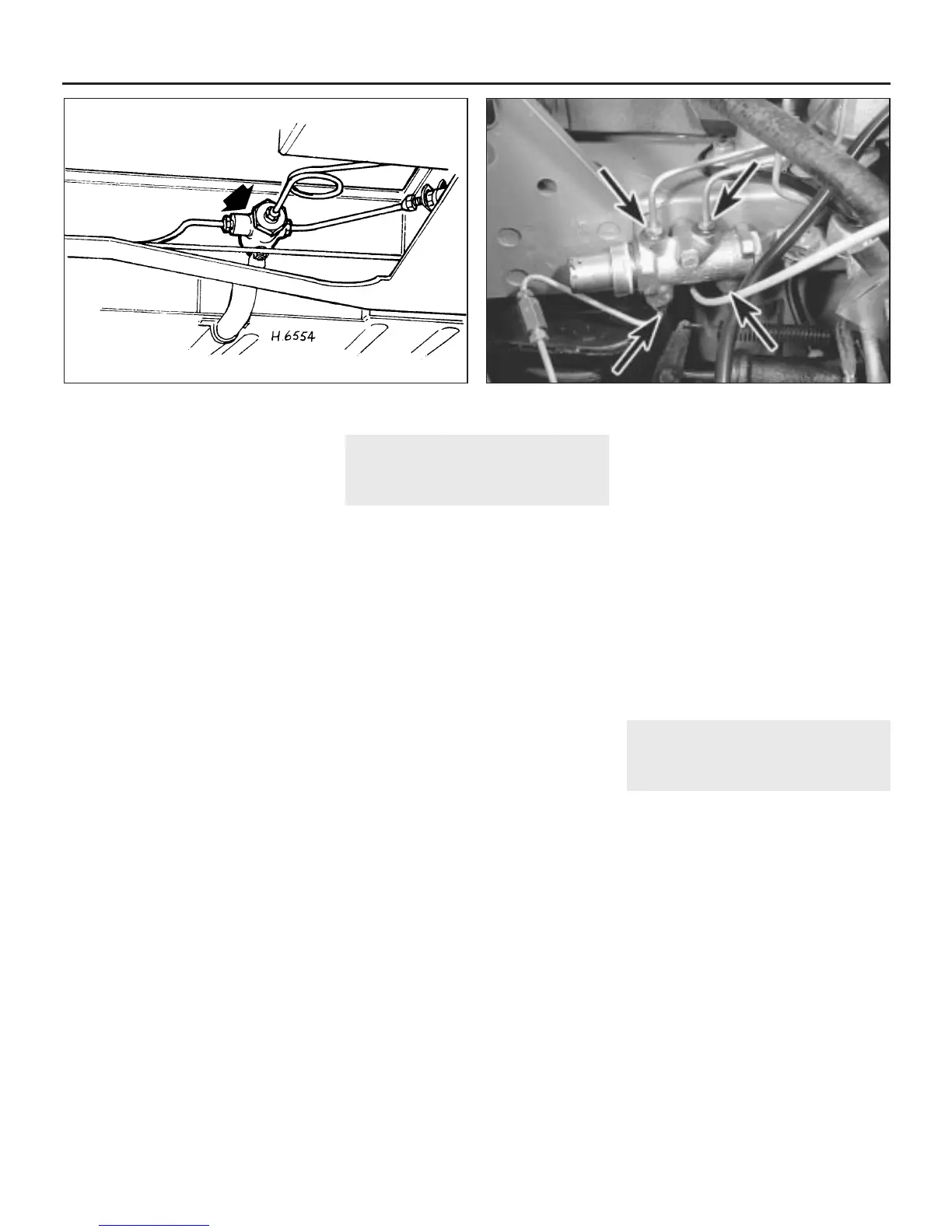
3 Thoroughly clean the exterior of the valve,
located on the rear subframe, ensuring that all
dirt and grit is removed from the area around
the brake pipe unions (see illustration).
4 Undo and remove the three hydraulic
unions and lift the brake pipes out of the
valve. Protect the ends of the pipes to prevent
possible dirt ingress.
5 Undo and remove the retaining nut and bolt
and lift the valve off its mounting.
Overhaul
6 Clamp the valve in a vice and remove the
large end plug and sealing washer.
7 Lift out the valve assembly and return
spring.
8 Thoroughly clean the components in clean
hydraulic fluid or methylated spirit and dry
with a lint-free cloth.
9 Examine the valve, cylinder bore and rubber
seals for wear and renew as necessary.
Rubber seals are not supplied separately, and
if they appear swollen or worn it will be
necessary to obtain a new valve assembly
complete with seals.
10 Lubricate the components in clean
hydraulic fluid and then refit the spring and
valve assembly into the valve body. Now refit
the end plug and sealing washer.
Refitting
11 Refitting the valve is the reverse sequence
to removal. Bleed the hydraulic system as
described in Section 2 on completion. If
hydraulic fluid loss has been kept to a
minimum it should only be necessary to bleed
the rear brakes.
19 Pressure reducing valve
(dual circuit system) -
removal and refitting
3
Note: On certain models fitted with dual
circuit braking systems a pressure reducing
valve is used to limit the braking force at the
rear wheels. The operation of the valve is
similar to the pressure regulating valve used
on single circuit systems. Before starting work,
refer to the warning at the beginning of
Section 2 concerning the dangers of hydraulic
fluid.
Removal
1 Remove the brake master cylinder filler cap,
top-up the reservoir, and place a thin piece of
polythene over the filler neck. Secure the
polythene with an elastic band or by refitting
the cap. This will reduce hydraulic fluid loss
when the brake pipes are disconnected from
the valve.
2 Unscrew the four pipe unions from the
reducing valve and carefully lift out the pipes.
Protect the disconnected unions to prevent
possible dirt ingress (see illustration).
9•16 Braking system
18.3 Location of pressure regulating valve on rear subframe 19.2 Pressure reducing valve hydraulic pipe unions
 Loading...