actions of both spring and shock absorber is
fitted to each suspension assembly, in place
of the rubber cone. The displacer units are
interconnected front-to-rear on each side of
the vehicle and are filled with a water-based,
non-corrosive fluid under pressure. The
principles of operation of the hydrolastic
suspension system are described in detail in
Section 2.
The steering gear is of the conventional
rack-and-pinion type with tie-rods connected
to the swivel hub steering arms by tie-rod
outer balljoints. Further balljoints on the inner
ends of the tie-rods are screwed into the rack.
The upper splined end of the helically toothed
pinion protrudes from the rack housing and
engages with the splined end of the steering
column. The pinion spline is grooved and the
steering column is held to the pinion by a
clamp bolt which partially rests in the pinion
groove.
2 Hydrolastic suspension
system - principles of
operation
Component layout
The Hydrolastic suspension system
consists of a Hydrolastic unit (known as a
displacer) fitted to the suspension assembly
at each wheel, and two metal pipes which
interconnect the displacer units on each side
of the vehicle, front to rear. The system is
filled with a water-based, non-corrosive
antifreeze fluid under pressure.
Each displacer consists of a rubber spring
fitted to the upper part of the unit. This rubber
spring is the actual springing and damping
medium, and is shaped in such a way as to
give a progressive rate characteristic similar
to the rubber cone spring fitted to non-
Hydrolastic Minis. At the lower end of the
displacer unit a tapered piston, attached to a
diaphragm operates within a tapered cylinder.
The diaphragm seals off the lower part of the
displacer and the piston is coupled to the
suspension assembly. Internally the displacer
unit is divided into an upper and lower
chamber by a separator plate, which also
contains the damper valves and a bleed hole.
Operation
Movement of the vehicle suspension
actuates the displacer piston, causing fluid to
be displaced through the separator plate and
into the upper chamber either via the bleed
hole, if suspension movement is small, or
through the damper valve if the movement is
more vigorous. This causes the upper
chamber to deflect upwards against the
resistance of the rubber spring, thus damping
the suspension movement. In addition to this,
fluid in the upper chamber will be displaced
via the transfer pipe to the displacer unit
connected to the other suspension assembly,
on the same side of the car. This will cause
the piston in this displacer to move
downwards and act on the suspension,
ensuring that the vehicle remains in a level
attitude. In the event of both suspension
assemblies on the same side of the car
deflecting together (ie body roll when
cornering), no fluid movement between the
two displacers will occur and the entire fluid
pressure will be applied simultaneously to
both displacer pistons giving a very high
resistance to the rolling movement.
As the relative front end weight of the Mini
is high, the normal ride attitude of the car
would be tail high, as the partially deflected
front suspension would transfer fluid to the
rear suspension, causing it to rise. To
overcome this, non-adjustable coil hold-down
springs are fitted between the chassis and
each rear suspension arm. Thus, fluid is
transferred from rear to front and a near level
attitude is maintained.
Servicing
The Hydrolastic system is completely
sealed, and therefore virtually maintenance
free. It is advisable, however, at periodic
intervals, to inspect the external condition of
the displacer units, hoses and pipe unions.
Any seepage of fluid from the union between
displacer hose and transfer pipe, or from any
other part of the system, will cause the vehicle
suspension to sag on the affected side.
It will be necessary when working on
certain suspension components to remove or
disconnect the displacer units or transfer
pipes. Before doing this, the system must be
depressurised by a Rover dealer who will have
the equipment required to remove the fluid
and evacuate the system. The vehicle can be
driven for short distances at slow speeds (ie
below 30 mph/48 kph) in a depressurised
condition, providing it is driven carefully. On
completion of the work the system must be
repressurised, again by a dealer.
The pressure in the system determines the
trim height of the vehicle and this should also
be checked periodically to ensure that it has
not altered appreciably. The trim height is
measured from the centre of the front wheel
hub to the top of the wheel arch. It is
important to ensure that the correct height is
maintained otherwise the steering geometry
may be affected, resulting in uneven tyre wear
and insensitive handling.
3 Front swivel hub - removal
and refitting
3
Removal
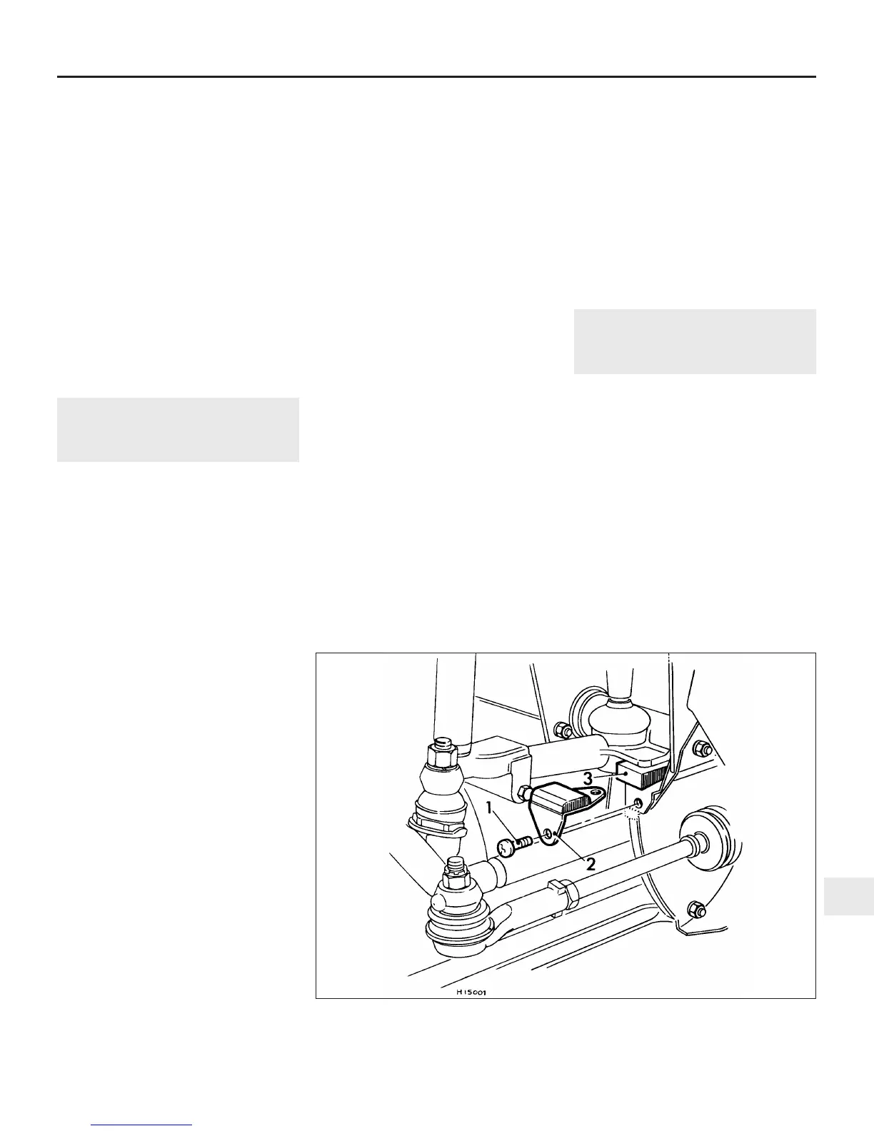
1 Working under the wheel arch, undo and
remove the single retaining screw and lift out
the upper suspension arm rebound rubber.
Position a solid packing piece of
approximately the same thickness in its place
(see illustration).
2 Chock the rear wheels then jack up the
front of the car and support it on axle stands
(see “Jacking and vehicle support”). Remove
the front roadwheel.
3 Extract the split pin from the driveshaft
retaining nut and, with an assistant firmly
depressing the brake pedal, undo and remove
the driveshaft nut using a socket and
extension bar. Remove the washer or split-
collar, as applicable, located behind the
Suspension and steering 10•3
10
3.1 Fitting a solid packing wedge in place of the suspension rebound rubber
1 Screw 2 Rebound rubber 3 Packing piece
 Loading...