driveshaft nut. Note that on disc brake
models, the driveshaft retaining nut is
extremely tight and it may be beneficial to
fabricate a home-made tool to prevent the
hub rotating when undoing the nut (see
Chapter 8, Section 2).
4 On disc brake models, undo and remove
the brake caliper retaining bolts. Lift off the
caliper complete with brake pads, and tie it
out of the way from a convenient place under
the wheel arch. On models fitted with drum
brakes, clamp the flexible brake hose with a
proprietary brake hose clamp or a self-
gripping wrench with its jaws suitably
protected. Now slacken the brake hose union,
at the wheel cylinder by half a turn.
5 Undo and remove the steering tie-rod
balljoint retaining locknut and then release the
balljoint tapered shank from the steering arm
using a universal balljoint separator (see
illustration).
6 Undo and remove the nuts and spring
washers securing the swivel hub balljoints to
the upper and lower suspension arms (see
illustration).
7 Using the method described in paragraph 5,
separate the upper and lower suspension
arms from the tapered shanks of the balljoints.
8 Carefully lift the swivel hub assembly off the
two suspension arms. At the same time, tap
the centre of the driveshaft, using a soft-faced
mallet, until the driveshaft can be withdrawn
from the rear of the swivel hub assembly.
9 On disc brake models, withdraw the swivel
hub assembly and then lift off the driving flange
and disc. On models with drum brakes,
support the flexible brake hose to avoid
stretching it and then rotate the complete
swivel hub assembly anti-clockwise to unscrew
it from the hose (see illustration). The hub can
now be lifted away and the end of the brake
hose protected to prevent dirt ingress. Collect
the copper sealing washer from the end of the
hose as the hose is removed. Note that a new
washer will be required for refitting.
Refitting
Models with drum brakes
10 Refitting is the reverse sequence to
removal, bearing in mind the following points:
a) Ensure that the hub bearing water shield
is in place on the driveshaft CV joint and
positioned approximately 6 mm from the
shoulder of the joint.
b) Use a new copper washer on the flexible
brake hose and ensure that the hose is
not twisted when refitting the swivel hub.
Bleed the hydraulic system at the
appropriate wheel on completion (see
Chapter 9).
c) Tighten all nuts and bolts to the specified
torque.
d) Tighten the driveshaft retaining nut to the
specified torque, then tighten the nut
further to align the split pin holes in the
driveshaft and nut. Secure the nut with a
new split pin.
Models with disc brakes
11 Refitting is the reverse sequence to
removal, bearing in mind points a and c
detailed in paragraph 10. Additionally, the
following procedure must be observed,
otherwise it is possible that the split-collar
fitted beneath the driveshaft retaining nut will
become clamped to the shaft before the shaft
is fully home in the hub bearings.
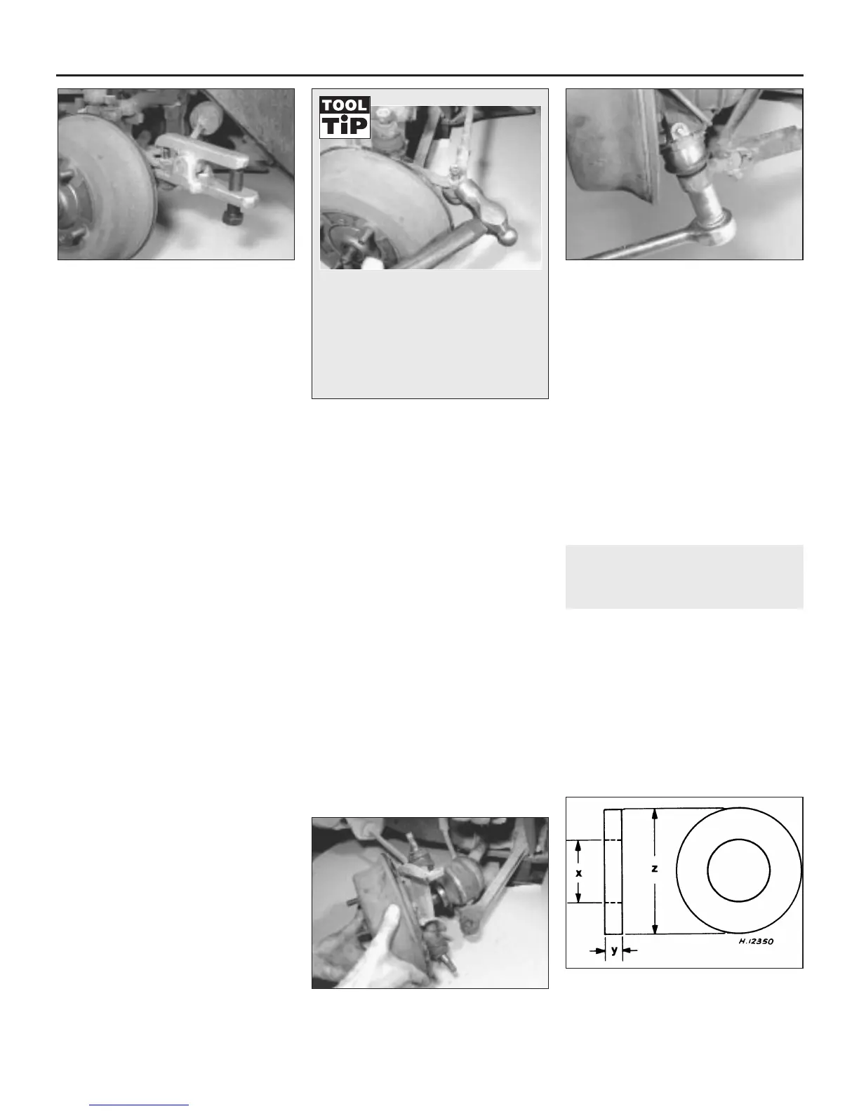
12 Insert the driveshaft through the swivel
hub, but do not fit the split collar. Obtain a
plain washer of the dimensions shown (see
illustration). If necessary, make the washer
from mild steel.
13 Fit the plain washer over the driveshaft
end. Fit the driveshaft retaining nut and, using
the same procedure as for removal to prevent
the hub rotating, tighten the nut to the
specified torque to seat the shaft in the hub
bearings. Note that there are two different
torque settings for the driveshaft nut; one for
driveshafts with multiple split pin holes, and a
higher setting for driveshafts with a single split
pin hole. Now remove the nut and washer and
smear engine oil over the driveshaft threads.
14 Examine the split-collar, and renew it if
damaged or worn. Fit the collar and driveshaft
retaining nut, and once again tighten it to the
specified torque. Tighten the nut further to
align the split pin holes in the driveshaft and
nut, then secure the nut with a new split pin.
4 Front hub bearings - renewal
3
Drum brake models
1 Remove the swivel hub assembly as
described in Section 3.
2 With the assembly on the bench, slacken
the brake adjusters, remove the two brake
drum retaining screws and lift off the drum. If
it is tight, tap it gently using a soft-faced
mallet.
3 Arrange two wooden blocks approximately
250 mm high, on the bench, far enough apart
for the drive flange to lie freely between them,
10•4 Suspension and steering
3.5 Remove the steering tie-rod balljoint
with a universal separator
3.6 Remove the lower swivel hub balljoint
retaining nut
3.12 Details of special washer required for
fitting the driveshaft on disc brake models
X = 25 mm Y = 6.5 mm Z = 50 mm
3.9 Withdraw the swivel hub from the end
of the driveshaft
An alternative method of releasing the
balljoint tapered shank is to refit the
locknut to the balljoint and screw it on
two or three turns. Using a medium
hammer, sharply strike the end of the
steering arm until the shock separates
the taper. Now remove the locknut and
lift the joint off the arm.
 Loading...