the rack sideways slightly until the pin fully
engages with the hole in the rack, thus
centralising the assembly. Engage the
steering inner column clamp with the pinion
shaft ensuring that the steering wheel spokes
are horizontal/centre spoke vertical.
11 Refit the column clamp bolt and then
remove the centralising pin. Refit the plastic
plug and grommet.
12 Refit the upper column support clamp
bolt, using a new shear bolt on later models.
Ensure that there is no twist or strain on the
column as the bolt is inserted. Reposition the
clamp and bracket if necessary.
13 The remainder of the refitting procedure
now varies according to model year as
described below.
Models with single stalk multi-
function switch
14 Tighten the steering column clamp and
bracket retaining bolts and the steering rack
U-bolt locknuts to the specified torque.
15 Reconnect the electrical multiplugs under
the parcel shelf.
16 Adjust the direction indicator switch
cancelling stud so that it just trips the switch
levers as the wheel is turned.
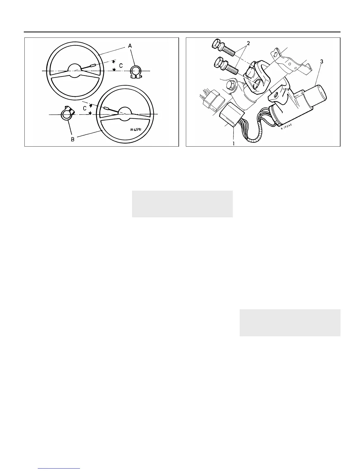
17 With the roadwheels in the straight ahead
position and the steering column installed, the
direction indicator stalk should be at 20º to the
horizontal, with the cancelling levers of the
switch (see illustration). If this is not the case,
slacken the steering column support bracket
clamp and rotate the column as necessary.
18 Refit the steering column shrouds and the
carpets, then reconnect the battery.
Models with twin stalk multi-function
switch
19 Position the outer column to give 2 mm
clearance between the steering wheel hub and
the boss of the multi-function switch, then
tighten the shear bolt until the head breaks off.
20 Reconnect the electrical multiplugs under
the parcel shelf.
21 Refit the steering column shrouds and the
carpets, then reconnect the battery.
24 Steering column -
dismantling and reassembly
3
Dismantling
1 With the steering column removed from the
car as described in Section 23, remove the
steering wheel as described in Section 22.
2 Undo and remove the retaining screws and
withdraw the multi-function switch from the
column.
3 On early models, undo and remove the
direction indicator cancelling stud and locknut
from the inner column.
4 The inner column can now be withdrawn
from the lower end of the outer column tube.
Before doing this insert the ignition key into
the switch and turn it to the I position. This will
release the steering lock and allow the inner
column to be removed.
5 Prise the top bush out of the column if
necessary using a screwdriver. The lower felt
bush is removed by simply sliding it out of the
outer column.
6 To remove the steering lock/ignition switch,
drill out the shear bolt heads, or alternatively
drill a hole in the shear bolts and unscrew
them using a stud extractor (see illustration).
The clamp plate and lock switch assembly
can then be removed.
7 With the steering column assembly
dismantled, check the inner and outer column
for straightness by rolling them on a flat surface.
Renew the parts if distortion is obvious.
Reassembly
8 Begin reassembly by lubricating the upper
polythene bush with graphite grease. Insert
the bush into the top of the outer column,
chamfered end first. Tap the bush fully into
position, ensuring that the shouldered slot
engages with the detent in the outer column.
9 Insert the inner column into the lower end of
the outer column and slide it in approximately
half way.
10 Soak the lower felt bush in engine oil and
then wrap it around the inner column until its
ends are butted together. Now carefully slide
the inner column fully home.
11 Refit the multi-function switch assembly,
and on early models the direction indicator
cancelling stud and locknut.
12 Refit the steering lock ignition switch
using new shear bolts. Do not shear the heads
off the bolts until the steering column has
been refitted and the operation of the steering
lock tested.
13 Refit the steering column to the car as
described in Section 23 then, when the column
is correctly positioned in relation to the steering
gear, refit the steering wheel (Section 22).
25 Steering tie-rod outer
balljoint - removal and
refitting
3
Removal
1 Chock the rear wheels then jack up the
front of the car and support it on axle stands
(see “Jacking and vehicle support”). Remove
the front roadwheel.
2 Slacken the locknut securing the balljoint to
the steering tie-rod by a quarter of a turn.
3 Undo and remove the balljoint shank locknut
and separate the taper of the shank using a
universal balljoint separator or the alternative
method described in Section 3, paragraph 5.
4 Hold the steering tie-rod with a self-
gripping wrench and unscrew the balljoint
from the tie-rod, counting the number of turns
necessary to remove it.
10•16 Suspension and steering
23.17 Correct position of clamp bolt and direction indicator lever
when refitting the early type steering column
A RHD models B LHD models C = 20º
A Multiplug
connector
2 Shear bolts 3 Steering
lock/ignition switch
24.6 Steering lock/ignition switch assembly
 Loading...