14 Undo and remove the two bolts securing
each of the four subframe mountings to the
body (see illustration). If the bolts are tight,
use liberal amounts of penetrating oil on them
and allow time for the oil to soak.
15 With the mounting bolts removed, engage
the help of an assistant to steady the
subframe and then slowly lower the jacks until
the subframe can be withdrawn from the rear
of the car.
16 With the subframe removed from the car it
can now be completely dismantled by
referring to the relevant Sections and
Chapters of this manual.
Refitting
17 Refitting is the reverse sequence to
removal, bearing in mind the following points:
a) Line up the subframe mountings and fit
the bolts finger tight first, before
progressively tightening.
b) Bleed the complete hydraulic system on
completion as described in Chapter 9.
c) On models fitted with Hydrolastic
suspension, have the system
repressurised at your nearest Rover
dealer.
22 Steering wheel - removal and
refitting
1
Removal
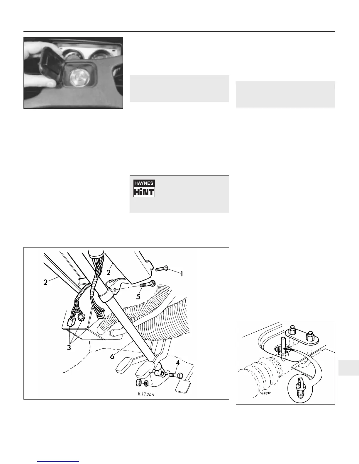
1 Depending on model, either undo and
remove the retaining screws and lift off the
trim, or carefully prise up the steering wheel
central motif (see illustration).
2 Using a suitable socket or box spanner,
undo and remove the nut which retains the
wheel on the steering column.
3 Recover the retaining nut lockwasher and
then lift the steering wheel off the splines on
the column.
Refitting
4 Make sure that the roadwheels are in the
straight-ahead position and that the small
triangle on the direction indicator switch bush
is pointing toward the horn push (later models
only).
5 Refit the steering wheel to the column with
the wheel spokes centralised.
6 Refit the lockwasher and retaining nut, then
tighten the nut to the specified torque.
7 Refit the trim or central motif.
23 Steering column - removal
and refitting
2
Removal
1 Disconnect the battery negative lead.
2 Undo and remove the screws securing the
two halves of the steering column shroud to
the column and lift off the shroud.
3 Disconnect the electrical wiring multiplug
connectors located under the parcel shelf
(see illustration).
4 At the base of the column, undo and
remove the pinch-bolt securing the inner
column clamp to the pinion shaft.
5 Undo and remove the upper column
support clamp bolt at the parcel shelf. On
later models where a shear bolt is used, cut a
slot in the bolt and use a screwdriver to
unscrew it, or drill a small hole and remove it
with a stud extractor.
6 Position the roadwheels in the straight-
ahead position, pull the column upwards and
remove it from the car.
Refitting
7 Make sure that the roadwheels are still in
the straight-ahead position.
8 Lift up the front carpets and slacken the
steering rack U-bolt locknuts sufficiently to
allow sideways movement of the rack housing.
9 Slacken the upper column support clamp
mounting bracket bolts, to allow movement of
the bracket.
10 Lift out the rubber grommet in the
passenger side floor, then remove the plastic
plug from the rack housing. Insert a 6 mm
diameter centralising pin (a bolt or drill bit are
ideal) into the hole (see illustration). Move
Suspension and steering 10•15
10
22.1 Prise up the central motif for access
to the steering wheel nut on later models
23.3 Steering column removal
1 Column shroud retaining screw
2 Column shroud halves
3 Multi-plug connectors
4 Pinch-bolt
5 Upper column support clamp bolt
6 Steering column
23.10 Use of a dowel to centralise the
steering rack
Inset shows plastic plug
If the wheel is tight, tap it up
near the centre, using the
palm of your hand, or twist it
from side to side, whilst
pulling upwards to release it from the
shaft splines.
 Loading...