the filler neck, then refit the cap. This will help
prevent fluid loss when the rear pipes are
disconnected.
7 From underneath the rear of the car, undo
and remove the brake hydraulic pipe union
from the centre of the pressure regulating valve
on early models. On models equipped with a
dual circuit braking system, unscrew the pipe
unions at the pipe connectors on each side of
the subframe front crossmember. On later dual
circuit systems unscrew the pipe union from
the three-way connector on the rear subframe.
8 Refer to Chapter 4C if necessary and
remove the complete exhaust system from
the car.
9 If an electric fuel pump is fitted, disconnect
the electrical leads, slacken the clips and
detach the fuel inlet and outlet hoses from the
pump.
Warning: Refer to the
precautions contained in
Chapter 4A, Section 1 before
carrying out any work on the
fuel system.
Note: During this operation, clamp the hoses
using a self-gripping wrench with suitably
protected jaws to prevent loss of fuel. Plug
both hoses with a bolt or suitable metal rod
upon removal.
10 On models fitted with Hydrolastic
suspension, undo and remove the transfer
pipe unions from the pressure valves at the
rear of the subframe.
11 Place a block of wood under the rear wheels
or jack up the radius arms slightly. From inside
the car or luggage compartment, undo and
remove the shock absorber upper mounting on
models with rubber cone suspension, or the
helper spring upper mounting on models with
Hydrolastic suspension. On Saloon cars, it will
be necessary to detach the fuel tank retaining
strap and move the tank slightly to provide
access to the left-hand mounting.
12 Undo and remove the retaining screws
and lift off the finisher panels from each end of
the body side sills (where fitted).
13 Place a jack under each side of the
subframe, or a trolley jack in the centre, with a
substantial plank of wood running
transversely across the subframe, and just
take the weight of the frame on the jacks.
10•14 Suspension and steering
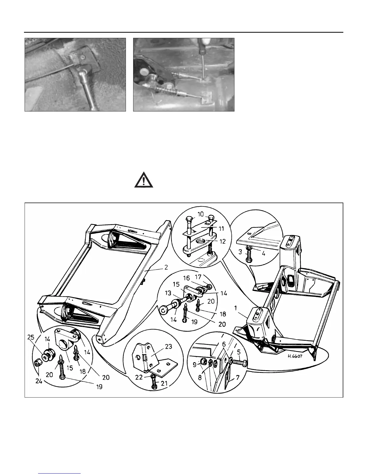
21.5a Hold the cable guide retaining nuts
from below . . .
21.5b . . . and unscrew from above
21.14 Exploded view of the front and rear subframe assemblies
1 Front subframe
2 Rear subframe
3 Screw
4 Washer
5 Bolt
6 Washer
7 Packing piece
8 Washer
9 Nut
10 Screw
11 Washer
12 Pressure pad
13 Support pin
14 Bush
15 Mounting
16 Washer
17 Nut
18 Screw
19 Screw
20 Washer
21 Screw
22 Washer
23 Bracket
24 Nut
25 Washer
 Loading...