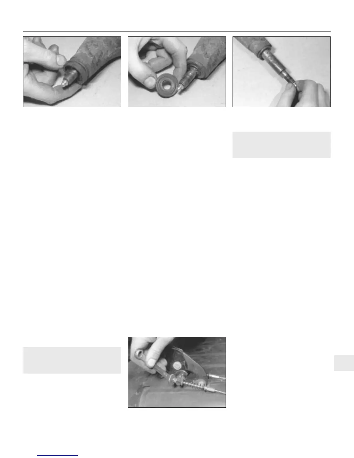
12 Lift off the rubber seal and thrustwasher
from each end of the pivot shaft and then
slide the pivot shaft out of the bearings (see
illustrations).
13 Wipe away all traces of grease from the
pivot shaft and the bearings, and carefully
inspect these components. Signs of wear will
be most obvious on the pivot shaft in the form
of scoring, pitting, wear, ridges or
deterioration of the surface hardening. If any
of these conditions are apparent, the shaft
and bearings require renewal.
14 The removal and refitting of both the
bearings, and the line reaming of the bronze
bearing to suit the outside diameter of the
pivot shaft, entails the use of several special
tools. As there is no other way of satisfactorily
carrying out this work, it is strongly
recommended that the arm is taken to a
Rover dealer for the complete bearing
removal, refitting and reaming to be carried
out.
Refitting
15 Refitting is the reverse sequence to
removal bearing in mind the following points:
a) When refitting the ball end of the knuckle
joint to the seat in the radius arm, pack
the cup seat with Dextragrease GP (or a
suitable alternative) available from Rover
dealers.
b) Bleed the hydraulic system at the
disconnected side as described in
Chapter 9.
c) When refitting is complete, have the
Hydrolastic system repressurised at your
nearest Rover dealer.
20 Rear subframe mountings -
renewal
3
Note: The subframe front and rear mountings
and rubber bushes can be renewed with the
subframe still in position in the car as
described below.
Front mounting
1 Remove the relevant radius arm assembly
from the car as described in Section 19.
2 Undo and remove the nut and washer
securing the support bolt to the subframe.
3 Undo and remove the two bolts and spring
washers securing the mounting to the body.
4 Lever the subframe down slightly and lift off
the mounting assembly.
5 The support bolt and rubber bushes can
now be removed from the mounting.
6 Refitting is the reverse sequence to
removal, noting that the step in the mounting
and the short bolt must be at the top (where
applicable).
Rear mounting
7 Chock the front wheels then jack up the
rear of the car and support it on axle stands
(see “Jacking and vehicle support”). Remove
the rear roadwheel.
8 Undo and remove the nut and washer
securing the mounting to the subframe.
9 On Estate, Van and Pick-up models, undo
and remove the two bolts securing the
mounting to the body. On Saloon models
have an assistant hold the bolts from inside
the luggage compartment while the retaining
nuts are removed from below.
10 Lever the subframe down slightly and
slide the mounting assembly sideways and off
the subframe.
11 The rubber bushes can now be removed
from the mounting.
12 In all cases, refitting is the reverse
sequence to removal, noting that the step in
the mounting and the short bolt must be at the
front.
21 Rear subframe - removal and
refitting
3
Note: Corrosion of the rear subframe is a
common occurrence on Minis, particularly
older models, and is one of the main causes of
MOT test failure on these cars. Where
corrosion has reached an advanced stage,
renewal of the subframe is the only
satisfactory cure. Despite its reputation for
being an extremely difficult task, removal of
the rear subframe is in fact a fairly
straightforward operation. Before carrying out
this work on cars fitted with Hydrolastic
suspension, it will be necessary to have the
system depressurised by a Rover dealer.
Removal
1 Chock the front wheels then jack up the
rear of the car and support it on axle stands
(see “Jacking and vehicle support”).
2 Where the battery positive lead is routed
through the subframe, disconnect the
negative, then the positive lead from the
battery terminals and pull the positive lead
clear of the frame, noting its routing for
reference when refitting.
3 On early models undo and remove the two
adjusting nuts securing the ends of the two
handbrake cables to the trunnion on the
handbrake lever (see illustration). Pull the
cables out of the trunnion and then slide off
the washers and tension spring. Note: On
later models a single front cable is used and
the tension springs are omitted.
4 Lift up the carpets to expose the cable
guide plates located at the point where the
cable passes through the floor.
5 Engage the help of an assistant to hold the
nuts from underneath the car while the cable
guide retaining screws are removed from
above (see illustrations). Lift off the guides
and sealing pads, and from underneath the
car, pull the ends of the cable through the
opening in the floor and out of the passenger
compartment.
6 Remove the brake master cylinder reservoir
filler cap and place a piece of polythene over
Suspension and steering 10•13
10
19.12a Lift off the radius arm bearing
rubber seal . . .
19.12b . . . and thrustwasher . . . 19.12c . . . then slide out the pivot shaft
21.3 Remove the handbrake cable
adjusting nuts
 Loading...