b) As the radius arm is lifted to refit the
helper spring, ensure that the strut
correctly locates in the knuckle joint and
displacer.
c) When refitting is complete, have the
Hydrolastic system repressurised at your
nearest Rover dealer.
17 Rear shock absorber (models
with rubber cone suspension)
- removal and refitting
3
Removal
1 Chock the front wheels then jack up the
rear of the car and support it on axle stands
(see “Jacking and vehicle support”). Remove
the rear roadwheel.
2 If removing the left-hand shock absorber on
Saloon models, or either of the rear shock
absorbers on Cooper S models equipped with
twin fuel tanks, it will first be necessary to
remove the fuel tank(s) as described in the
relevant Part of Chapter 4.
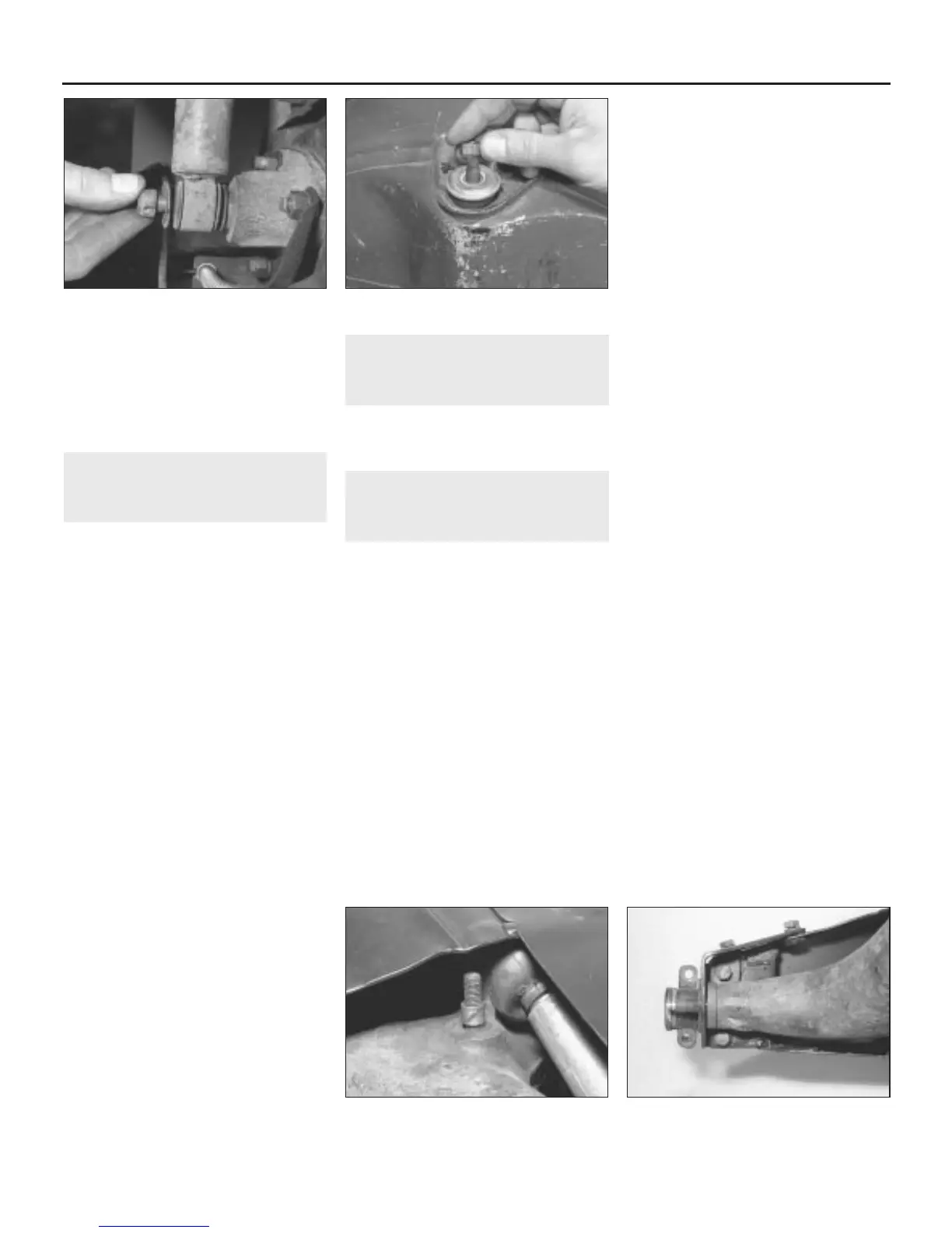
3 Support the radius arm using a jack or
block of wood, then undo and remove the
shock absorber retaining locknut and washers
from the radius arm (see illustration).
4 Working inside the car or luggage
compartment, lift off the protective rubber
cap, then undo and remove the two locknuts
from the upper end of the shock absorber
(see illustration).
5 Lift off the thrustwasher and rubber bush,
and then withdraw the shock absorber from
under the car.
6 Examine the shock absorber for leaks or
damage to the outer casing. Hold the shock
absorber upright, and fully compress and
extend it six times. Now slowly compress and
extend it once more. If “dead” areas are
apparent, if there is free travel when changing
direction, or if the unit is damaged or leaking,
it must be renewed.
Refitting
7 Refitting is the reverse sequence to
removal. Hold the shock absorber in an
upright position and fully compress and
extend it six times to expel any air before
installing.
18 Rear helper spring (models
with Hydrolastic suspension)
- removal and refitting
3
The procedure is the same as described in
Section 17 for removal and refitting of the
shock absorber.
19 Rear radius arm - removal
and refitting
3
Note: Before carrying out this operation on
cars fitted with Hydrolastic suspension, it will
be necessary to have the Hydrolastic system
depressurised by a Rover dealer.
Removal
1 Remove the rear shock absorber as
described in Section 17 if working on vehicles
fitted with rubber cone suspension, or the rear
helper spring (Section 18) if Hydrolastic
suspension is fitted.
2 Lower the radius arm as far as it will go.
When working on vehicles fitted with rubber
cone suspension, extract the spring strut from
the cone spring. Then pull the strut rearwards,
to disengage the ball end of the knuckle joint
from its cup seat in the radius arm. If
Hydrolastic suspension is fitted, pull the
displacer strut rearwards to disengage the
strut from the knuckle joint (or the ball end of
the knuckle joint from its seat) and then move
the strut forwards and out of the displacer
unit.
3 Undo and remove the retaining screws and
lift off the finisher panel from the end of the
body side sills (where fitted).
4 On models fitted with Hydrolastic
suspension, undo and remove the retaining
screw and lift off the bump rubber from the
subframe.
5 Clamp the flexible brake hose, located over
the top of the radius arm, with a brake hose
clamp or self-gripping wrench with jaws
suitably protected. Now undo the union nut
securing the metal pipe to the hose and undo
and remove the nut securing the hose to its
bracket. Plug the ends of the hose and pipe
after removal to prevent dirt ingress.
6 Extract the split pin and withdraw the clevis
pin securing the end of the handbrake cable
to the brake operating lever. Detach the cable
and tension spring from the bracket at the
rear of the brake backplate.
7 The handbrake cable moving sector is
secured to the front of the radius arm either by
a through-bolt and lower locknut, or by an
upper retaining spire clip, thrustwasher and
spring washer. In the case of the through-bolt,
undo and remove the lower locknut and then
remove the sector from the bolt. Take care not
to lose the small distance tube from the centre
of the sector (see illustration). If the sector is
retained by a spire clip, prise the clip off the
upper end of the pivot pin, lift off the washers
and then withdraw the sector and pivot from
the radius arm.
8 From underneath the car undo and remove
the radius arm pivot shaft inner retaining nut
and spring washer. Undo and remove the
pivot shaft outer retaining nut and washer.
9 Undo and remove the four bolts securing
the radius arm outer bracket to the subframe.
Note that two of these bolts can only be
removed using a socket and extension or box
spanner inserted between the radius arm and
subframe or bracket (see illustration). Lift
away the bracket.
10 Carefully lift the radius arm off the
subframe, taking care not to lose the
thrustwashers and rubber seal fitted at each
end of the radius arm pivot shaft.
11 If there is any doubt about the condition of
the radius arm pivot bearings, they should be
inspected as follows.
10•12 Suspension and steering
17.3 Remove the shock absorber lower . . . 17.4 . . . and upper mounting
19.7 The small distance piece is fitted to
the handbrake moving sector
19.9 Rear radius arm outer bracket
retaining bolts (subframe shown removed)
 Loading...