7 Withdraw the distance piece (if fitted)
located between the two bearings and then
drive out the two outer races away from the
hub centre.
8 Thoroughly clean all the parts in paraffin or
a suitable solvent and dry with a lint-free
cloth.
9 Carefully examine the bearing inner and
outer races, and the ball cage and balls for
scoring, pitting or wear ridges; renew as
necessary. The hub oil seal must be renewed
as it will have been damaged during removal.
If the bearings are in a satisfactory condition,
reassemble the balls and ball cage to the
outer race and then press the inner race back
into position.
10 Before refitting the bearings remove any
burrs that may be present in the bore of the
hub. Use a fine file or scraper.
11 Pack the bearings using a general
purpose lithium based grease and fit the
inboard bearing to the hub with the narrow
edge of the bearing outer race facing away
from the hub centre. Press or tap the bearing
into position, using the outer race only, with a
tube of suitable diameter until the bearing
abuts the shoulder in the hub. Take great care
to keep the bearing square as it is installed,
otherwise it will jam in the hub bore, and could
cause the outer race, to crack.
12 Fit a new oil seal to the rear of the hub
with its lip facing towards the bearing. On
models fitted with taper roller bearings, the oil
seal lip faces away from the bearing.
13 Place the distance piece in position and fit
the outboard bearing into the hub, again
ensuring that the narrow edge of the bearing
outer race faces away from the hub centre.
Note: Some makes of plain ball-bearings have
lengthened inner races which butt against
each other. In this case the bearing distance
piece is no longer needed.
14 With the bearings installed, refit the hub to
the stub axle and gently tap it home using a
soft-faced mallet. Ensure that the stub axle
squarely enters the distance piece between
the two bearings.
15 Place the thrustwasher over the stub axle,
chamfered side toward the bearing, then refit
the securing nut and tighten it to the specified
torque. Align the next split pin hole and fit a
new split pin.
16 Refit the hub cap, brake drum and
roadwheel, readjust the brakes (see Chapter 1)
then lower the car to the ground.
15 Rear rubber cone spring -
removal and refitting
3
Removal
1 Chock the front wheels then jack up the
rear of the car and support it on axle stands
(see “Jacking and vehicle support”). Remove
the rear roadwheel.
2 Support the radius arm using a jack or
block of wood, then undo and remove the
shock absorber retaining locknut and washers
from the arm. Slide the end of the shock
absorber off the radius arm stud then remove
the jack and lower the arm as far as it will go.
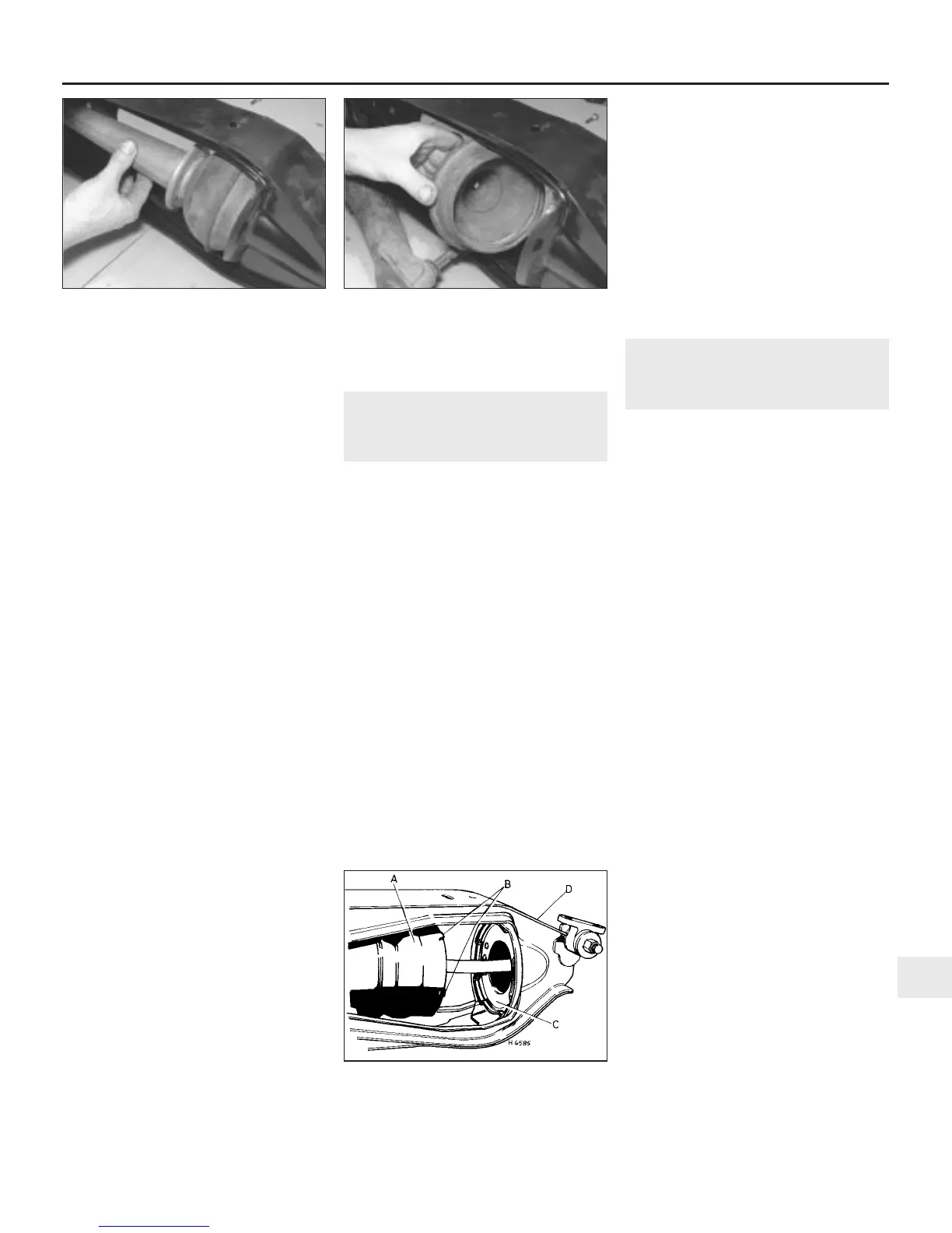
3 Using a screwdriver or thin flat bar, prise
the rear end of the spring strut out of the
rubber cone (see illustration). Now
disengage the ball end of the knuckle joint at
the front of the spring strut from its seat and
lift the strut off the car.
4 The rubber cone spring can now be levered
off its location in the subframe and withdrawn
from the car (see illustration).
Refitting
5 Before refitting the rubber cone spring, drift
the ball end of the knuckle joint out of its
location in the spring strut; examine it and its
seat in the radius arm for scoring, corrosion
and damage. Renew the complete knuckle
joint if worn. If the joint is in a satisfactory
condition, pack the cup seat with
Dextragrease GP (or a suitable alternative)
available from Rover dealers, then refit the ball
end of the knuckle joint to the cup seat.
Ensure that the rubber dust cover is correctly
located, otherwise water and grit will enter the
joint.
6 The remainder of refitting is the reverse
sequence to removal. When refitting the
shock absorber, be sure that the spring strut
and knuckle joint are properly engaged as the
radius arm is raised.
16 Rear Hydrolastic displacer
unit - removal and refitting
3
Note: To enable the displacer unit to be
removed it will first be necessary to have the
Hydrolastic system depressurised by a Rover
dealer.
Removal
1 Chock the front wheels then jack up the
rear of the car and support it on axle stands
(see “Jacking and vehicle support”). Remove
the rear roadwheel.
2 Place a block of wood or a jack beneath the
rear radius arm, then undo and remove the
nut, spring and flat washers securing the
helper spring to the radius arm.
3 Lower the radius arm as far as it will go.
4 Undo and remove the single retaining
screw and lift the bump rubber off the
subframe.
5 Disconnect the flexible Hydrolastic hose
from its union at the rear of the subframe.
6 Pull the displacer strut rearwards to
disengage the knuckle joint ball from its seat,
then withdraw the strut from the displacer
unit.
7 Rotate the displacer anti-clockwise and lift
it from its location on the subframe.
Refitting
8 Before refitting the displacer unit, examine
the knuckle joint ball end (assuming that it
was released from its seat as the strut was
removed) and seat for scoring, pitting or
corrosion. Renew the complete knuckle joint if
worn. If the joint is in a satisfactory condition,
pack the cup seat with Dextragrease GP (or a
suitable alternative) available from Rover
dealers, then refit the ball end of the knuckle
joint to the cup seat. Ensure that the rubber
dust cover is correctly located, otherwise
water and grit will enter the joint.
9 The remainder of refitting is the reverse
sequence to removal, bearing in mind the
following points:
a) When installing the displacer, turn it
clockwise to lock it into the registers on
the subframe locating plate (see
illustration).
Suspension and steering 10•11
10
15.3 Remove the rear rubber cone spring
strut . . .
15.4 . . . and rubber cone spring
16.9 Rear Hydrolastic displacer unit
separated from locating plate
A Displacer unit
B Locating lugs
C Locating plate
D Subframe
 Loading...