each line. A line drawn on the floor starting at
the front and finishing at the rear should be
quite straight and pass through the centres of
the other lines. Diagonal measurements can
also be made as a check for squareness.
6 On older Minis, rust or corrosion of the
vehicle underframe is a common occurrence
and, if the corrosion has reached an advanced
state, may be grounds for failure of the annual
MoT test.
7 Where serious rust or corrosion has
affected a load bearing area, it will be
necessary to have this repaired immediately
either by fitting a new body section or, in less
serious cases, by plating over the affected
area. The load bearing areas of the Mini
consist of the subframe, the side sills (inner
and outer) and any area of the vehicle
structure within 305 mm of a suspension,
steering, subframe, or seat belt anchorage
point.
8 Repairs of this nature are best left to a body
repair specialist, as any new section or plating
that may be necessary must be welded in
place to restore the original structural rigidity
of the bodyshell. The repair of corrosion to
structural areas using fibreglass, body filler, or
the retention of new sections with pop rivets,
or screws, is not acceptable to legal
requirements.
6 Front door interior trim panel
(Saloon and Estate models) -
removal and refitting
1
Removal
1 Undo and remove the two screws and lift
off the interior pull handle (see illustration).
2 Undo and remove the retaining screws and
lift away the door lock remote control handle
followed by the window regulator handle and
surround (see illustrations). On later models,
the screw securing the window regulator
handle is covered with a trim cap, which must
be carefully prised out for access to the screw.
11•4 Bodywork and fittings
6.1 Remove the interior pull handle
retaining screws and handle
6.2a Remove the door lock remote control
handle . . .
6.2b . . . and the window regulator handle
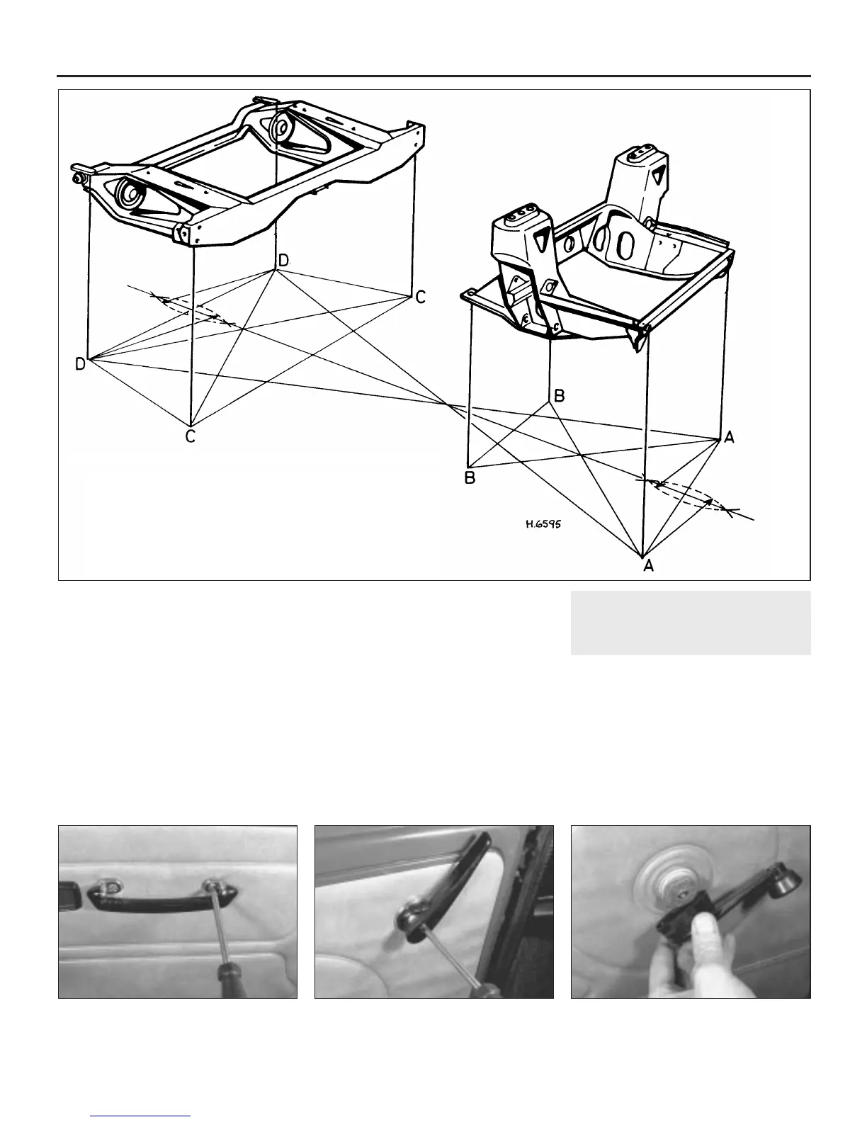
5.5 Body and subframe horizontal alignment check
AA Width between centres of the front subframe front mounting
bolts = 660.4 mm
BB Width between centres of the front subframe rear mounting
bolts = 412.65 mm
CC Width between centres of the rear subframe front mounting
block lower bolts = 1282.7 mm
DD Width between centres of the rear subframe rear mounting
block bolts = 977.9 mm
 Loading...