Finding a short-circuit
15 To check for a short-circuit, first
disconnect the load(s) from the circuit (loads
are the components which draw current from
a circuit, such as bulbs, motors, heating
elements, etc).
16 Remove the relevant fuse from the circuit,
and connect a circuit tester or voltmeter to the
fuse connections.
17 Switch on the circuit, bearing in mind that
some circuits are live only when the ignition
switch is moved to a particular position.
18 If voltage is present (indicated either by
the tester bulb lighting or a voltmeter reading,
as applicable), this means that there is a
short-circuit.
19 If no voltage is present during this test,
but the fuse still blows with the load(s)
reconnected, this indicates an internal fault in
the load(s).
Finding an earth fault
20 The battery negative terminal is
connected to “earth” - the metal of the
engine/transmission and the vehicle body -
and many systems are wired so that they only
receive a positive feed, the current returning
via the metal of the car body. This means that
the component mounting and the body form
part of that circuit. Loose or corroded
mountings can therefore cause a range of
electrical faults, ranging from total failure of a
circuit, to a puzzling partial failure. In
particular, lights may shine dimly (especially
when another circuit sharing the same earth
point is in operation), motors (eg wiper
motors) may run slowly, and the operation of
one circuit may have an apparently-unrelated
effect on another. Note that on many vehicles,
earth straps are used between certain
components, such as the engine/transmission
and the body, usually where there is no metal-
to-metal contact between components, due
to flexible rubber mountings, etc.
21 To check whether a component is
properly earthed, disconnect the battery and
connect one lead of an ohmmeter to a known
good earth point. Connect the other lead to
the wire or earth connection being tested. The
resistance reading should be zero; if not,
check the connection as follows.
22 If an earth connection is thought to be
faulty, dismantle the connection, and clean
both the bodyshell and the wire terminal (or
the component earth connection mating
surface) back to bare metal. Be careful to
remove all traces of dirt and corrosion, then
use a knife to trim away any paint, so that a
clean metal-to-metal joint is made. On
reassembly, tighten the joint fasteners
securely; if a wire terminal is being refitted,
use serrated washers between the terminal
and the bodyshell, to ensure a clean and
secure connection. When the connection is
remade, prevent the onset of corrosion in the
future by applying a coat of petroleum jelly or
silicone-based grease, or by spraying on (at
regular intervals) a proprietary ignition sealer,
or a water-dispersant lubricant.
3 Fuses and relays - general
information
1
Main fuses
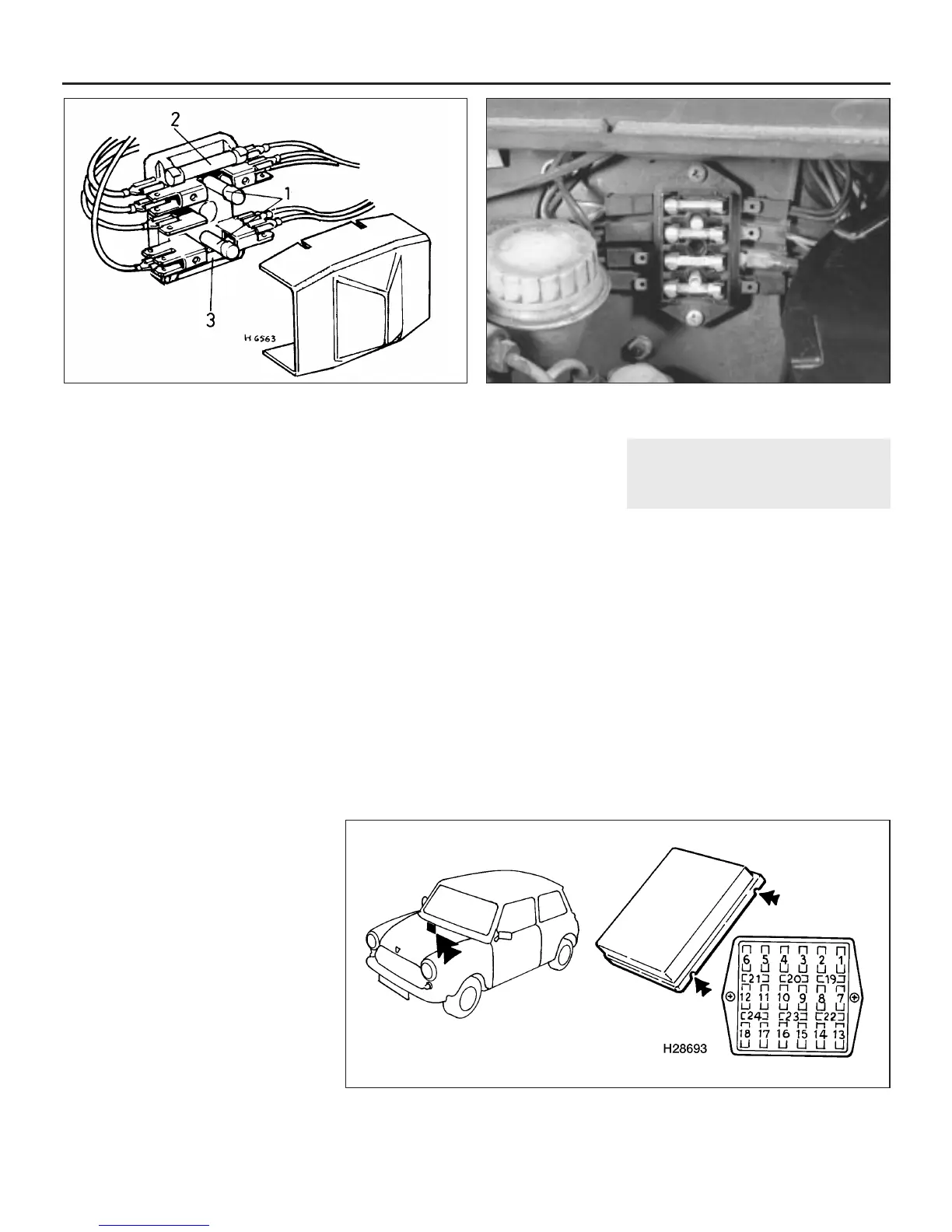
1 The main fuses are located in a block which
is mounted on the right-hand wing valance on
early models, and on the right-hand side of the
engine compartment bulkhead on later models
(see illustrations). The fuse block is covered
by a plastic push-on cover. Upon inspection it
will be seen that there are two main fuses on
early models and either four or twenty four
main fuses on later versions. In both cases,
spare fuses are contained within the fuse
block or cover. The fuse positions and circuits
protected are listed in the Specifications.
2 To remove a fuse, simply withdraw it from
the contacts in the fuse block; the wire within
the fuse should be visible; if the fuse is blown,
the wire will be broken or melted. Before
refitting a new fuse ensure that the contacts
12•4 Body electrical system
3.1a Two-fuse type fuse block details
1 Spare fuses 2 35 amp fuse 3 35 amp fuse
3.1b Four-fuse type fusebox location
3.1c Twenty-four fuse type fuse block location
Arrows indicate fuse block cover locating notches
 Loading...