are clean and free from corrosion. If
necessary the contacts may be cleaned with a
fine grade emery paper.
3 Always renew a fuse with one of an
identical rating; never use a fuse with a
different rating from the original or substitute
anything else. Never renew a fuse more than
once without tracing the source of the trouble.
4 Persistent blowing of a particular fuse
indicates a fault in the circuit(s) protected.
Where more than one circuit is involved, switch
on one item at a time until the fuse blows, so
showing in which circuit the fault lies.
5 Besides a fault in the electrical component
concerned, a blown fuse can also be caused
by a short-circuit in the wiring to the
component. Look for trapped or frayed wires
allowing a live wire to touch vehicle metal, and
for loose or damaged connectors.
6 After renewing a fuse, refit the fuse block
cover, ensuring that it is pushed fully into
place. The cover for the twenty four fuse
block, has two notches on one side to ensure
that it is fitted correctly.
Line fuses
7 A line fuse is fitted to protect an individual
unit or circuit. Line fuses are located in clusters
on the engine compartment bulkhead, behind
the facia or instrument panel, and under the
bonnet lock platform. The number of fuses,
and the circuits protected, depends on model
and equipment fitted. To change a line fuse,
hold one end of the container, press and twist
off the other end.
Relays
8 A relay is an electrically-operated switch,
which is used for the following reasons:
a) A relay can switch a heavy current
remotely from the circuit in which the
current is flowing, allowing the use of
lighter gauge wiring and switch contacts.
b) A relay can receive more than one control
input, unlike a mechanical switch.
c) A relay can have a timer function - for
example an intermittent wiper delay.
9 On later Mini models, relays are used to
operate a number of circuits, mainly in the
engine management and emission control
systems. The engine management system
relays are contained in a sealed module
mounted on the engine compartment
bulkhead - these cannot be individually
renewed and in the event of a fault in this
area, the complete module must be renewed.
A relay for the Lambda (oxygen) sensor is
mounted separately, also on the bulkhead.
Further information on the engine
management system relays will be found in
Chapter 4B and 4C.
10 Relays for circuits such as the direction
indicator/hazard flasher system, and auxiliary
cooling fan are also used according to model,
year, and equipment fitted.
11 If a circuit which includes a relay develops
a fault, remember that the relay itself could be
faulty. Testing is by substitution of a known
good relay. Do not assume that relays which
look similar are necessarily identical for
purposes of substitution.
12 Make sure that the ignition is switched off,
then pull the relay from its socket. Push the
new relay firmly in to refit.
4 Switches - removal and
refitting
2
Note: Disconnect the battery negative lead
before removing any switch and reconnect the
lead after refitting the switch.
Steering column multifunction
switch
Early type switches incorporating
direction indicator, horn and headlight
main beam control
1 Undo and remove the screws securing the
two halves of the steering column shroud to
the column and lift off the two halves.
2 Undo and remove the two screws securing
the switch retaining strap and lift the switch
off the column.
3 Disconnect the wiring harness connector
under the parcel shell and lift away the switch.
4 Refitting is the reverse sequence to
removal.
Later type switches incorporating
direction indicator, horn, headlight
main beam and windscreen
washer/wiper control
5 Undo and remove the retaining screws and
lift off the two halves of the steering column
shroud (see illustration).
6 Refer to Chapter 10 and remove the
steering wheel.
7 Disconnect the two switch multiplug
connectors under the parcel shelf (see
illustration).
8 Undo and remove the retaining screw and
lift out the direction indicator cancelling block.
9 Slacken the switch clamp screw and slide
the switch off the end of the steering column.
10 If it is wished to renew either of the
switches they may be renewed as a complete
assembly or individually. If they are to be
renewed individually, it will be necessary to
drill out the two rivets securing the
windscreen washer/wiper switch to the
mounting plate and unwrap the insulating
tape securing the harness together.
11 Refitting is the reverse sequence to
removal. Ensure that the striker dog on the
nylon switch centre is in line with and adjacent
to the direction indicator switch stalk.
Facia switches
12 Undo and remove the lower heater
retaining nut and the two screws securing the
front of the heater to the parcel shelf. Lower
the heater to the floor. Note: On models fitted
with a centre console, it will be necessary to
remove the console and facia glovebox
retaining screws to allow the console to be
moved if necessary for access.
13 On models fitted with toggle switches,
unscrew the locking ring securing the switch
to the panel and withdraw the switch to the
rear. Make a note of the electrical connections
at the rear of the switch and disconnect them.
Body electrical system 12•5
12
4.5 Remove the securing screws and lift
off the steering column shroud
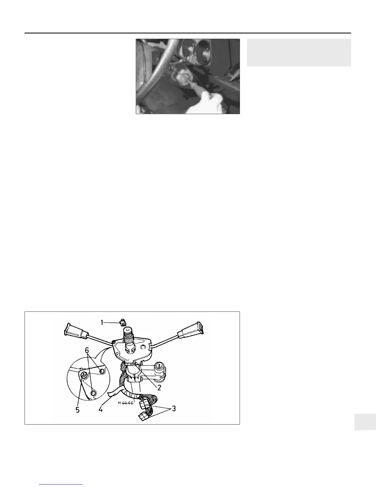
4.7 Steering column multifunction switch
1 Cancelling ring drive block
2 Clamp screw
3 Multi-plug connectors
4 Insulating tape
5 Screw
6 Rivet
 Loading...