14 On models fitted with rocker switches
simply push the switch out of the panel and
detach the multiplug (see illustration).
15 In both cases refitting is the reverse
sequence to removal.
Door pillar switch
16 The interior light door pillar switches are
retained by either being a push fit in the
pillars, or by a single securing screw. Prise out
the push fit type or remove the screw,
disconnect the electrical lead and lift away the
switch.
17 The switch is refitted in the reverse way.
Stop light switch
Note: The stop lights are operated either
hydraulically by a pressure sensitive switch
incorporated in the braking system or
electrically by an on/off switch mounted above
the brake pedal.
Hydraulically operated type
18 Remove the brake master cylinder filler
cap and place a piece of polythene over the
filler neck. Now refit the cap. This will prevent
loss of hydraulic fluid when the stop light
switch is removed.
19 Lift up the rubber cover, if fitted, and
disconnect the two wires from the stop light
switch located on the right-hand side of the
front subframe beneath the flywheel housing
(see illustration).
20 Using a large socket and extension bar,
remove the switch from the pipe connector.
21 Refitting the switch is the reverse
sequence to removal. If precautions were
taken to prevent fluid loss, it should not be
necessary to bleed the hydraulic system.
However, if the brake pedal now feels spongy,
bleed the system as described in Chapter 9.
Electrically operated type
22 Disconnect the two wires at the switch,
accessible from below the parcel shelf.
23 Undo and remove the locknut and then
withdraw the switch from its mounting
bracket.
24 Refitting is the reverse sequence to
removal. Adjust the position of the switch and
locknuts so that the stop lights operate after
6.3 mm of brake pedal travel.
Ignition switch
25 Undo and remove the securing screws
and lift off the two halves of the steering
column shroud.
26 Disconnect the ignition switch multiplug
connector (see illustration).
27 Inspect the top of the ignition switch
housing, and if a small screw is present,
unscrew it. The ignition switch can now be
withdrawn from the steering lock housing.
28 If a small retaining screw is not visible,
then the ignition switch is of the sealed type
and can only be removed with the steering
lock housing as a complete assembly. This
procedure is described fully in Chapter 10
Section 24.
29 Refitting the ignition switch is the reverse
sequence to removal.
Reversing light switch
(manual transmission models)
Note: The following procedures apply to later
Mini Saloon models having reversing lights
incorporated in the rear light clusters. The
12•6 Body electrical system
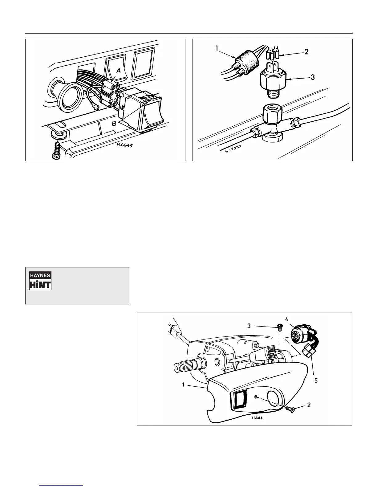
4.14 Removal of rocker type facia switch
A Multi-plug connector B Switch retaining tabs
4.19 Hydraulic stop light switch removal
1 Rubber cover (where
fitted)
2 Electrical leads
3 Stop light switch
4.26 The later type ignition/starter switch
1 Steering column shroud
2 Shroud retaining screw
3 Ignition switch securing
screw
4 Ignition switch
5 Multiplug connector
Tape the wiring to the door
pillar, to prevent it falling
back into the pillar.
Alternatively, tie a piece of
string to the wiring to retrieve it.
 Loading...