switch is located in the gearchange remote
control housing and is actuated by the
gearchange lever when reverse is selected.
30 Chock the rear wheels then jack up the
front of the car and support it on axle stands
(see “Jacking and vehicle support”).
31 Working underneath the car, disconnect
the two switch wires, slacken the locknut and
unscrew the switch from the remote control
housing.
32 Refitting is the reverse sequence to
removal.
33 Adjustment is carried out as follows. With
the wires disconnected, screw the switch into
the housing until slight resistance is felt.
34 Connect the wires, select reverse gear
and switch on the ignition. Continue screwing
the switch in until the reversing lights just
come on and then screw the switch in a
further quarter of a turn.
35 Tighten the locknut and check that the
reversing lights are illuminated with the gear
lever in reverse and extinguished in all other
gear positions. Lower the car to the ground on
completion.
Reversing light switch
(automatic transmission models)
36 Refer to Chapter 7B.
Starter inhibitor switch
(automatic transmission models)
37 Refer to Chapter 7B.
5 Bulbs (exterior lights) -
renewal
1
Note: With all light bulbs, remember that if
they have just been in use, they may be very
hot. Switch off the power before renewing a
bulb. With quartz halogen bulbs (headlights
and similar applications), use a tissue or clean
cloth when handling the bulb; do not touch
the bulb glass with the fingers. Even small
quantities of grease from the fingers will cause
blackening and premature failure. If a bulb is
accidentally touched, clean it with methylated
spirit and a clean rag.
Headlight
1 Either sealed beam or renewable bulb light
units are fitted to all Minis, depending on
model type and year of manufacture (see
illustration).
2 To remove the headlight unit on Clubman
and 1275 GT models, undo and remove the
four screws and lift off the grille panel
extension around the light unit. On all other
models undo and remove the outer rim
securing screw and ease the bottom of the
outer rim forwards, lift it up and off the
retaining lugs at the top of the light unit (see
illustrations).
3 Proceed as follows according to light unit
type.
Sealed beam type
4 Undo and remove the three small inner rim
securing screws and withdraw the inner rim
(see illustrations). Lift out the light unit.
Body electrical system 12•7
12
5.2a On Clubman models remove the grille
panel extension foe access to the
headlight
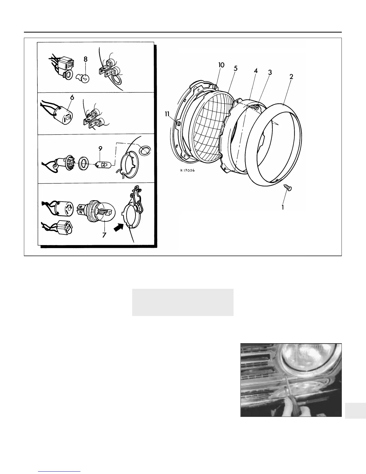
5.1 Headlight bulb assemblies
1 Outer rim retaining screw
2 Outer rim
3 Inner rim retaining screw
4 Inner rim
5 Light unit
6 Three-pin connector
7 Headlight bulb
8 Sidelight bulb (used with
sealed beam light unit)
9 Sidelight bulb (used with bulb
type light unit)
10 Vertical adjustment screw
11 Horizontal adjustment screw
 Loading...