5 Withdraw the three pin connector from the
rear of the reflector and lift away the complete
unit (see illustration).
6 Refitting is the reverse sequence to
removal.
Renewable bulb type
7 Undo and remove the three small inner rim
securing screws and withdraw the inner rim.
Lift out the light unit.
8 Withdraw the three pin connector from the
rear of the reflector and disengage the spring
clip from the reflector lugs. Lift away the bulb.
Note the locating pip on the reflector and
mating indentation in the bulb rim.
9 Refitting is the reverse sequence to
removal. Ensure that the indentation in the
bulb rim locates over the locating pip on the
reflector.
Alternative renewable bulb type
10 On certain models an alternative bulb type
headlight assembly of slightly different design
to the standard unit may be fitted (see
illustration).
11 To renew a bulb on these units, first
remove the outer rim as described in
paragraph 2.
12 Carefully pull the three adjusting screws
one at a time out of their locations and lift out
the reflector.
13 Withdraw the three pin connector from the
rear of the reflector and disengage the spring
clip from the reflector lugs. Lift away the bulb.
Note the position of the projection on the bulb
rim in relation to the bulb locator and ensure
that the new bulb is fitted correctly.
14 Refitting is the reverse sequence to
removal. Ensure that the projection on the
bulb rim is correctly engaged with the bulb
locator.
Auxiliary driving light -
Cooper models
15 Undo and remove the screw and release
the clamp securing the reflector to the light
unit.
16 Withdraw the reflector and disconnect the
bulb wiring connector.
17 Disengage the spring clip from the
reflector lugs and lift away the bulb.
18 Refitting is the reverse sequence to
removal.
12•8 Body electrical system
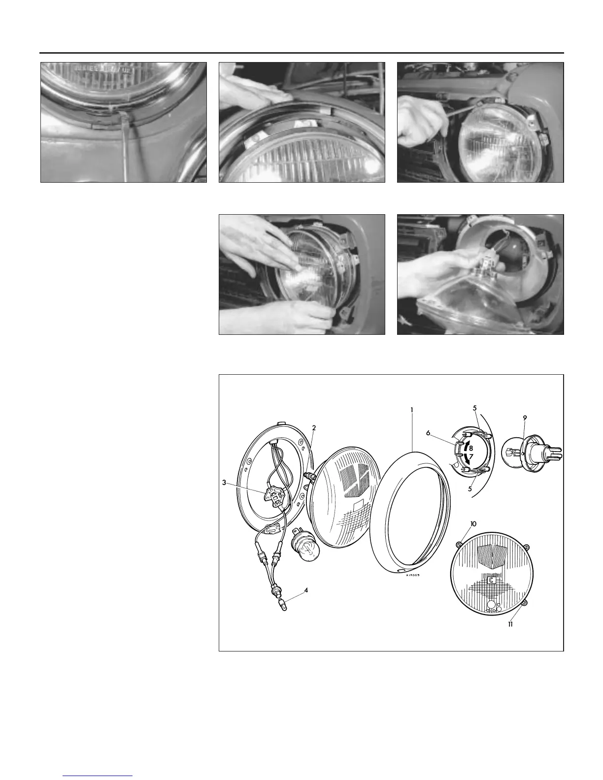
5.2b On non-Clubman models, undo the
outer rim securing screw . . .
5.2c . . . and lift the rim off the upper lugs 5.4a Unscrew the inner rim securing
screws . . .
5.4b . . . and lift off the inner rim 5.5 Detach the electrical connector and lift
away the light unit
5.10 Alternative type headlight assembly
1 Outer rim
2 Adjusting screws
3 Three pin connector
4 Sidelight bulb
5 Spring clip
6 Bulb locator
7 Position of bulb locator for
right-hand drive vehicles
8 Position of bulb locator for
left-hand drive vehicles
9 Projection on bulb
10 Horizontal adjustment
screw
11 Vertical adjustment screw
 Loading...