Front sidelight
All models except Clubman
and 1275 GT
19 Undo and remove the headlight outer rim
securing screw and ease the bottom of the
outer rim forwards, lift it up and off the
retaining lugs at the top of the light unit.
20 Undo and remove the three small
headlight inner rim securing screws and
withdraw the inner rim. Lift out the light unit.
21 Where a sealed beam headlight unit is
fitted, disconnect the headlight bulb wiring
connector and remove the sidelight bulb from
the wiring connector block; it will be either a
push-fit or bayonet type fitting.
22 Where a renewable bulb type light unit is
fitted, withdraw the sidelight bulbholder from
the rear of the reflector. Remove the bayonet
fitting type bulb from the holder.
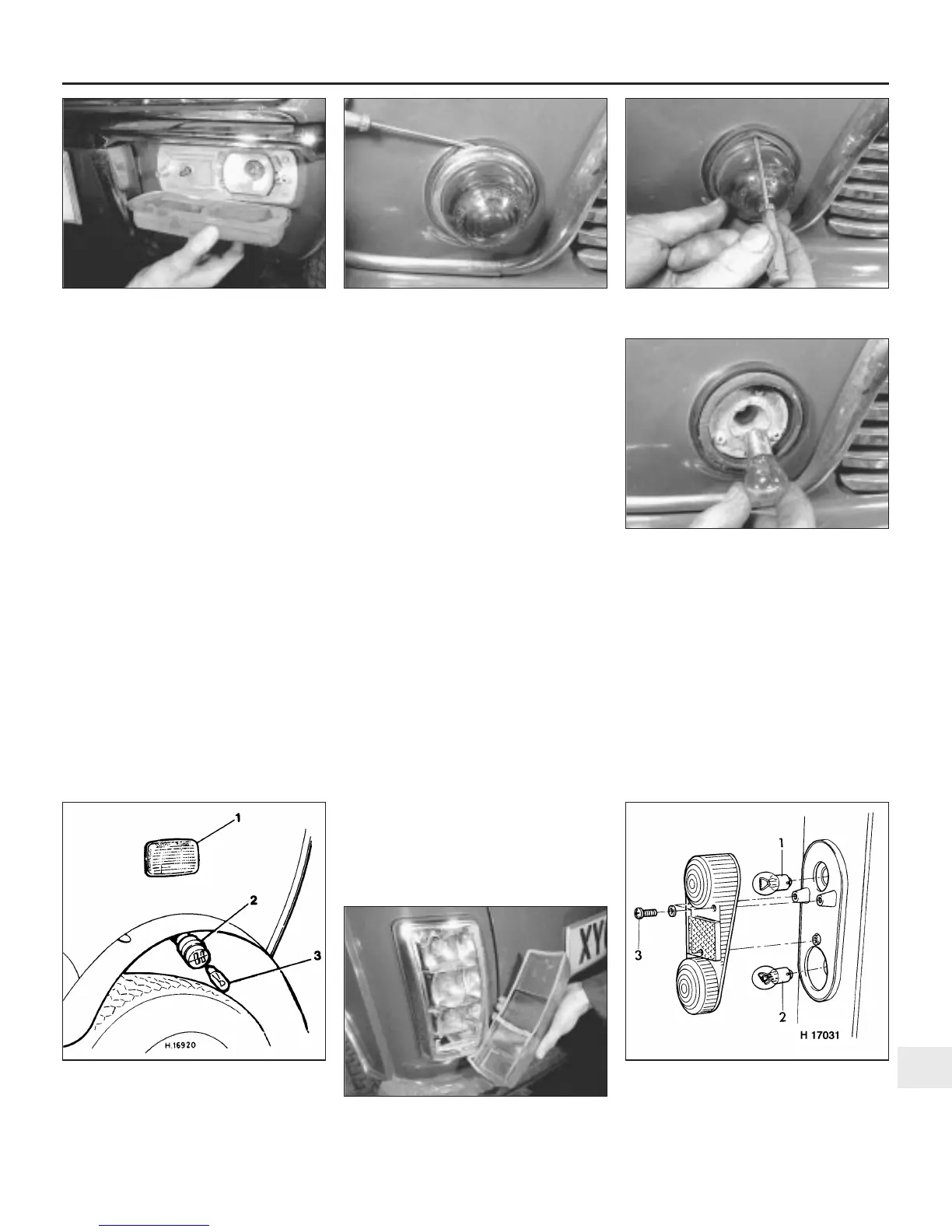
23 Refit the bulb and headlight unit using the
reverse sequence to removal.
Clubman and 1275 GT models
24 Undo and remove the two screws that
secure the lens to the light body. Carefully lift
away the lenses (see illustration).
25 Push in the bayonet fitting bulb slightly
and turn it anti-clockwise to remove.
26 Refitting is the reverse sequence to
removal. Take care not to over tighten the two
lens retaining screws as the lenses can be
easily cracked.
Front direction indicator
All models except Clubman
and 1275 GT
27 To renew a bulb, very carefully fold back
the rubber flange with the aid of a screwdriver
and remove the plated rim and lens (see
illustrations). On later models the lens is
secured by two screws.
28 Push the bulb in slightly and turn it anti-
clockwise to remove it (see illustration).
29 Refitting is the reverse of the removal
procedure, but ensure that the plated rim is
secured all round by the rubber flange, if
applicable.
Clubman and 1275 GT models
30 The procedure is the same as described
previously for the front sidelight bulb.
Front direction indicator side
repeater
31 Access to the rear of the light and the
bulbholder is gained through the front wheel
arch (see illustration).
32 Push the bulbholder in and rotate it, this
will release it from the rear of the light unit and
allow the holder and electrical lead to be
drawn down out of the wheel arch.
33 The push-fit bulb can now be removed
from the holder.
34 Refitting is the reverse of removal.
Stop/tail and rear direction
indicator
35 Undo the three screws to release the light
lenses (see illustrations).
36 The direction indicator bulb is fitted in the
top compartment and the stop/tail bulb in the
lower compartment (or centre compartment
on later models).
37 Both bulbs have bayonet fixings; to
remove push in slightly, and rotate anti-
clockwise.
38 Refitting is the reverse sequence to removal.
Take care not to overtighten the lens securing
screws as the lenses can easily be cracked.
Body electrical system 12•9
12
5.24 Undo the two screws and lift off the
lens
5.27a Fold back the rubber flange and
remove the rim . . .
5.27b . . . and lens
5.28 Push and turn the bulb anti-clockwise
to remove
5.31 Direction indicator side repeater
details
1 Light unit
2 Bulb holder
3 Bulb 5.35a Rear light cluster lens removed for
bulb renewal - Saloon models
5.35b Rear light bulb renewal - Estate, Van
and Pick-up models
1 Direction
indicator bulb
2 Stop/tail bulb
3 Securing screws
 Loading...