3 Undo and remove the three small screws
and lift out the instrument facing.
4 At the rear of the instrument panel, undo
and remove the two screws securing the
gauge to the panel body and remove the
gauge.
Speedometer
5 Ease off the spring clips securing the
speedometer lens glass and carefully remove
the glass, sealing rings and printed face plate.
6 At the rear of the instrument panel undo
and remove the two screws securing the
speedometer to the panel body and remove
the speedometer.
Tachometer
7 Detach the voltage stabiliser lead and bulb
holder from the rear of the tachometer.
8 Carefully prise up the pegs securing the
printed circuit to the tachometer body and lift
the unit away.
Printed circuit and voltage stabiliser
9 Pull the voltage stabiliser carefully out of its
location in the printed circuit at the rear of the
instrument panel (see illustration).
10 Withdraw the panel and warning light bulb
holders.
11 Where fitted, undo and remove the three
screws and the voltage stabiliser tag
connections for the tachometer.
12 Undo and remove the four screws
securing the fuel and temperature gauges.
13 Carefully prise out the plastic pegs
securing the printed circuit to the instrument
panel and lift off the printed circuit.
Reassembly
14 In all cases reassembly is the reverse of
the dismantling sequence.
17 Speedometer cable - removal
and refitting
3
Removal
Models with central instrument panel
1 Disconnect the battery negative lead.
2 Working in the engine compartment, detach
the speedometer cable from the rear of the
speedometer by unscrewing the knurled
retaining nut and pulling the cable into the
engine compartment.
3 Release the cable from the cable clip on the
bulkhead
Models with offset instrument panel
4 Disconnect the battery negative lead.
5 Hold both sides of the instrument nacelle
and carefully pull it off the instrument panel.
On some models the nacelle is secured by
screws.
6 Remove the upper trim strip to gain access
to the upper instrument panel retaining
screws.
7 Undo and remove the side and upper
retaining screws securing the instrument
panel to the mounting brackets.
8 Draw the panel outward slightly, depress
the lug on the side of the speedometer cable
connector and withdraw the cable off the end
of the speedometer.
9 Pull the cable through the bulkhead
grommet and into the engine compartment.
All models
10 Working under the car disconnect the
cable from the transmission. To gain access,
work through the aperture above the left-hand
driveshaft.
11 Should the cable securing nut be tight to
turn by hand, remove the bolt that secures the
speedometer drive and withdraw the cable
complete with the drive assembly. The cable
may then be detached from the drive
assembly.
Refitting
12 Refitting the speedometer cable is the
reverse sequence to removal but the following
additional points should be noted:
a) If the speedometer drive was removed,
always fit a new joint washer.
b) To lubricate the inner cable, withdraw the
inner cable and lightly grease it except for
200 mm at the speedometer end. Refit
the inner cable and wipe away any
surplus grease.
18 Radio - removal and refitting
3
Note: If the radio incorporates an anti-theft
system, once the battery has been
disconnected, the radio unit cannot be re-
activated until the appropriate security code
has been entered. Do not remove the unit
unless the appropriate code is known.
Removal
1 De-activate the radio security code (where
applicable).
2 Disconnect the battery negative lead.
Centre console mounted radio
3 Removal and refitting of the radio is
included in the centre console removal and
refitting procedures described in Chapter 11.
1989 onwards models with radio
beneath the facia
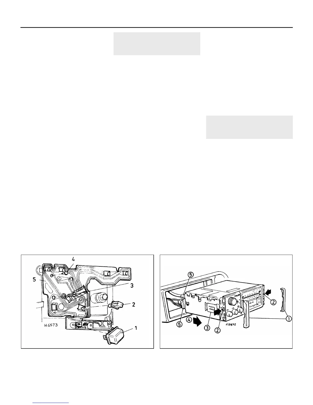
4 Prise the side covers from the radio, then
loosen the two small screws (see
illustration).
12•16 Body electrical system
16.9 Offset instrument panel printed circuit connections
1 Voltage stabiliser
2 Panel light
3 Fuel and
temperature gauge
securing screws
4 Printed circuit
securing stud
5 Printed circuit
18.4 Radio fixings on 1989-on models
1 Side covers
2 Retaining screws
3 Holding clips
4 Direction of removal
5 Multi-plug and aerial lead
 Loading...