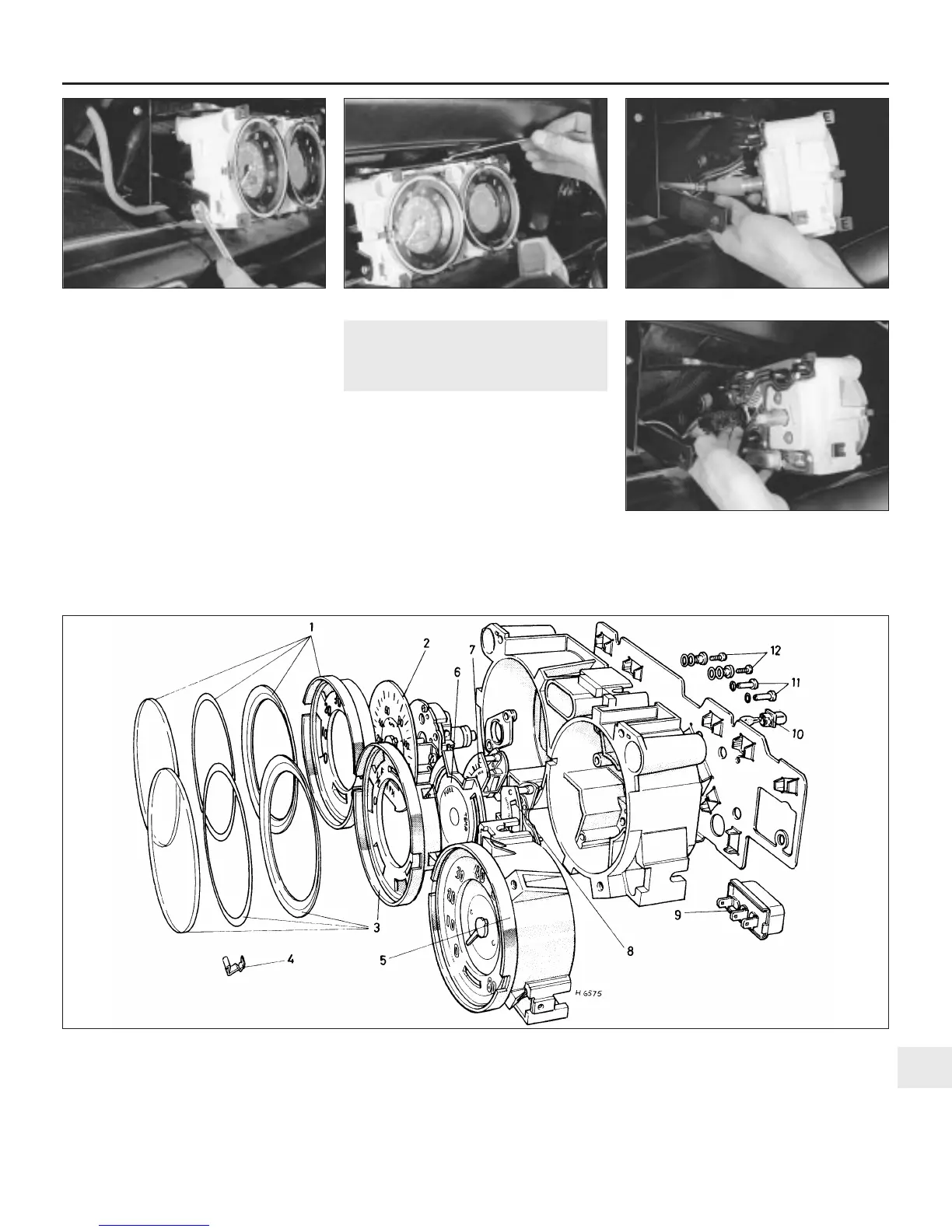
28 Draw the panel outward and detach the
speedometer cable, the wiring multiplug
connector and (where fitted) the two electrical
leads at the rear of the tachometer (see
illustrations).
29 Carefully lift away the instrument panel,
taking care not to damage the printed circuit.
Refitting
30 Refitting is the reverse sequence to
removal.
Models with wooden facia
31 Refer to the removal and refitting
procedures for the wooden facia as described
in Chapter 11, which include details of
instrument panel removal.
16 Instrument panel -
dismantling and reassembly
2
Note: On models fitted with a centrally
mounted panel the instruments and
components are withdrawn as part of the
instrument panel removal sequence (see
Section 15). The following procedure is
therefore applicable to models having an offset
instrument panel mounted in front of the driver.
Dismantling
1 Remove the instrument panel as described
in Section 15.
Fuel and temperature gauge
2 Ease off the spring clips securing the
instrument lens glass and carefully remove
the glass, sealing rings and printed face plate
(see illustration).
Body electrical system 12•15
12
15.27a Undo the side . . . 15.27b . . . and upper retaining screws 15.28a Detach the speedometer cable . . .
15.28b . . . and the multiplug connector,
then lift away the instrument panel
16.2 Exploded view of the offset instrument cluster
1 Speedometer lens and
faceplate assembly
2 Speedometer unit
3 Fuel/temperature gauge lens
and faceplate assembly
4 Lens securing clips
5 Tachometer assembly (where
fitted)
6 Fuel/temperature gauge facing
7 Fuel gauge
8 Temperature gauge
9 Voltage stabiliser
10 Panel lamp bulb and holder
11 Fuel/temperature gauge
securing screws
12 Speedometer securing screws
 Loading...