17 The cylinder head can now be removed
by lifting upwards. If the head is jammed, try
to rock it to break the seal. Under no
circumstances try to prise it apart from the
block with a screwdriver or cold chisel, as
damage may be done to the faces of the head
or block. If other methods fail to work, strike
the head sharply with a plastic or wooden
headed hammer, or with a metal hammer with
an interposed piece of wood to cushion the
blows. Under no circumstances must you hit
the head directly with a metal hammer, as this
may cause the iron casting to fracture.
Several sharp taps with the hammer, at the
same time pulling upwards, should free the
head. Lift the head off squarely and place it on
one side.
18 If the cylinder head is to be dismantled for
overhaul, refer to Part B of this Chapter. Refer
to Section 6 if the rocker shaft assembly is to
be dismantled.
Preparation for refitting
19 The mating faces of the cylinder head and
cylinder block must be perfectly clean before
refitting the head. Use a metal or hard plastic
scraper to remove all traces of gasket and
carbon; also clean the piston crowns. Take
particular care during the cleaning operations,
as the mating faces and piston crowns can be
easily scored. Also, make sure that the carbon
is not allowed to enter the oil and water
passages - this is particularly important for the
lubrication system, as carbon could block the
oil supply to the engine’s components. Using
adhesive tape and paper, seal the water and
oil holes in the cylinder block. To prevent
carbon entering the gap between the pistons
and bores, smear a little grease in the gap.
After cleaning each piston, use a small brush
to remove all traces of grease and carbon
from the gap, then wipe away the remainder
with a clean rag. Clean all the pistons in the
same way.
20 Check the mating surfaces of the cylinder
block and the cylinder head for nicks, deep
scratches and other damage. If slight, they
may be removed carefully with a file, but if
excessive, machining may be the only
alternative to renewal.
21 If warpage of the cylinder head gasket
surface is suspected, use a straight-edge to
check it for distortion. Refer to Part B of this
Chapter if necessary.
22 Check the condition of the cylinder head
studs and nuts, and particularly their threads.
Wash the nuts in a suitable solvent and wipe
clean the studs. Check each for any sign of
visible wear or damage, renewing any if
necessary.
Refitting
23 After checking that both the cylinder block
and cylinder head mating faces are perfectly
clean, generously lubricate each cylinder with
engine oil.
24 Always use a new cylinder head gasket as
the old gasket will be compressed and not
capable of giving a good seal. It is also easier
at this stage to refit the small bypass hose
from the water pump to the cylinder head.
25 The cylinder head gasket is marked
“FRONT” and “TOP” and should be fitted in
position according to the markings (see
illustrations).
26 With the gasket in position carefully lower
the cylinder head onto the cylinder block.
Make sure that the bypass hose engages with
the pipe stub on the cylinder head as the head
is lowered into place.
27 Fit the cylinder head nuts and washers
finger tight to the five cylinder head holding-
down studs, which remain outside the rocker
cover.
28 Fit the pushrods in the same order in
which they were removed. Ensure that they
locate properly in the stems of the tappets,
and lubricate the pushrod ends before fitting.
29 The rocker shaft assembly can now be
lowered over its eight locating studs. Take
care that the rocker arms are the right way
round. Lubricate the ball ends of the tappet
adjusting screws and insert them in the
pushrod cups. Note: Failure to place the ball
ends in the cups can result in them seating on
the edge of a pushrod or outside it when the
head and rocker assembly is pulled down
tight.
30 Fit the four rocker pedestal nuts and
washers, and then the four cylinder head stud
nuts and washers, which also serve to hold
down the rocker pedestals. Pull the nuts down
evenly, but without tightening them right up.
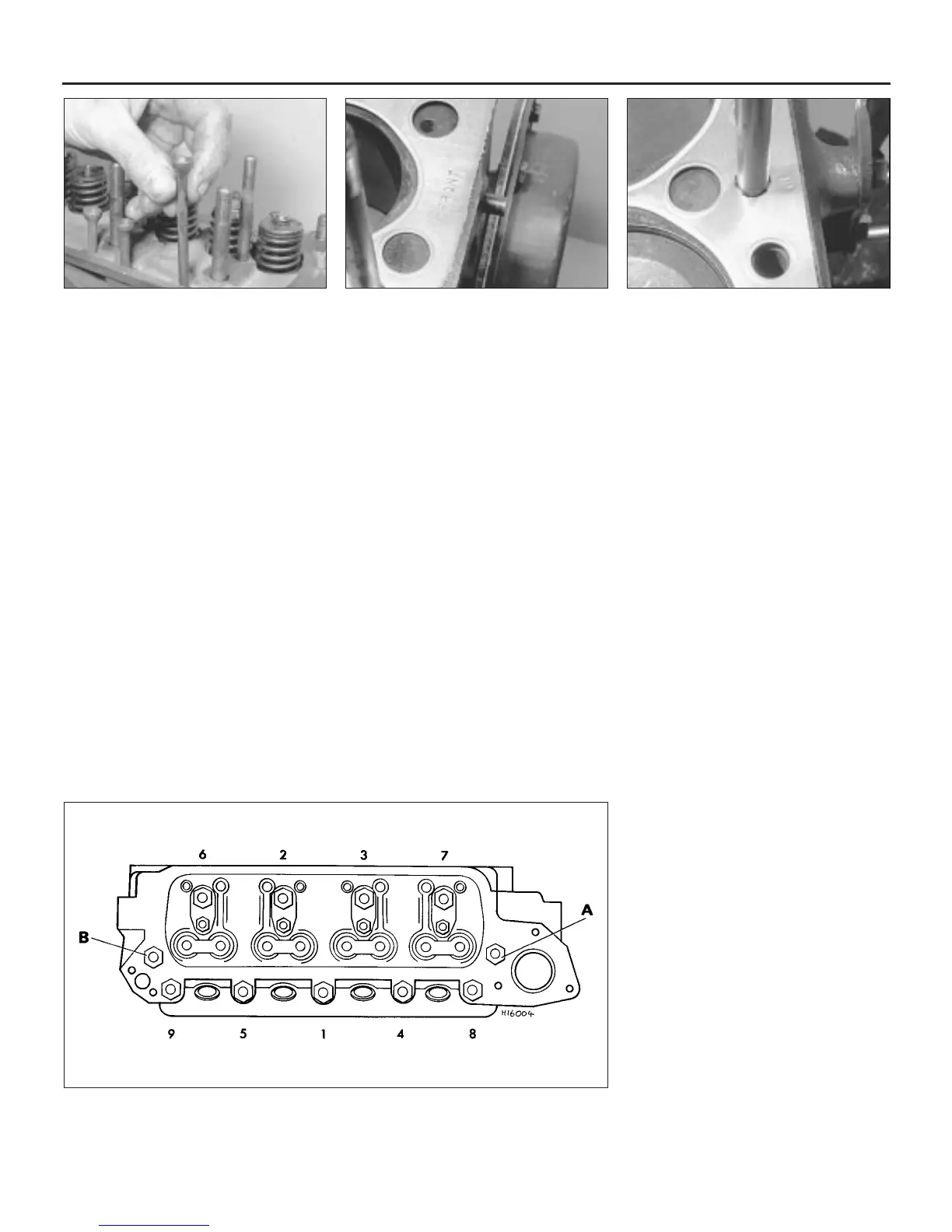
31 When all is in position, the nine cylinder
head nuts and the four rocker pedestal nuts
can be tightened down in the order shown
(see illustration). Turn the nuts a quarter of a
turn at a time and tighten to the specified
torque
Note: On 1275 cc engines having an
additional nut and bolt, these should be
tightened last.
2A•8 Engine in-car repair procedures
7.16 Remove the pushrods, keeping them
in order
7.25a The cylinder head gasket is marked
FRONT . . .
7.25b . . . and TOP
7.31 Cylinder head nut tightening sequence
A and B indicate additional bolt and nut on some 1275 cc engines. Reverse this order for slackening
 Loading...