33 Undo and remove the nut securing the
steering tie-rod balljoint to the steering arm on
each side of the car. Release the balljoint
tapers using a universal separator.
34 Undo and remove the nut securing the
front suspension swivel hub balljoint to the
upper suspension arm on each side of the car.
Release the balljoint shanks from the upper
suspension arms using universal balljoint
separator. Move the top of the two swivel
hubs outwards and allow them to hang in this
position. Take care not to strain the flexible
brake hoses excessively.
35 On early models equipped with rubber
couplings at the inner end of each driveshaft,
undo and remove the two U-bolt locknuts
securing each coupling to the differential
driving flanges. Withdraw the two U-bolts
from each side and move the driveshafts
away from the differential.
36 On later models equipped with offset
sphere joints at the inner end of each
driveshaft, release the joints from the
differential using Rover special tool 18G1240.
If this tool cannot be obtained, it is possible to
withdraw the joints using a tyre lever or similar
tool pivoting against the end cover retaining
bolt directly below the joint. Once the joints
have been released, move the driveshafts
away from the differential as far as possible.
37 On Cooper S and certain automatic
transmission models, undo and remove the
four nuts securing each universal joint flange
to the differential driving flanges. Move the
driveshafts away from the differential to
separate the flanges.
38 On all models undo and remove the nut
and bolt securing the exhaust pipe strap to
the bracket on the side of the differential
housing.
39 Undo and remove the nut and bolt
securing the lower engine tie-bar to the
bracket on the transmission casing. Slacken
the nut and bolt securing the other end and
remove the tie-bar clear of the transmission.
40 Position a crane or hoist over the engine
and attach chains or ropes either to brackets
bolted to the cylinder head or around each
end of the transmission casing.
41 With the lifting gear in position, raise it
slightly and just take the weight of the engine.
42 Undo and remove the two nuts and bolts
securing the two engine mountings to the side
of the front subframe.
43 Make a final check that all cables, pipes
and hoses have been disconnected and that
all removed parts are clear of the engine.
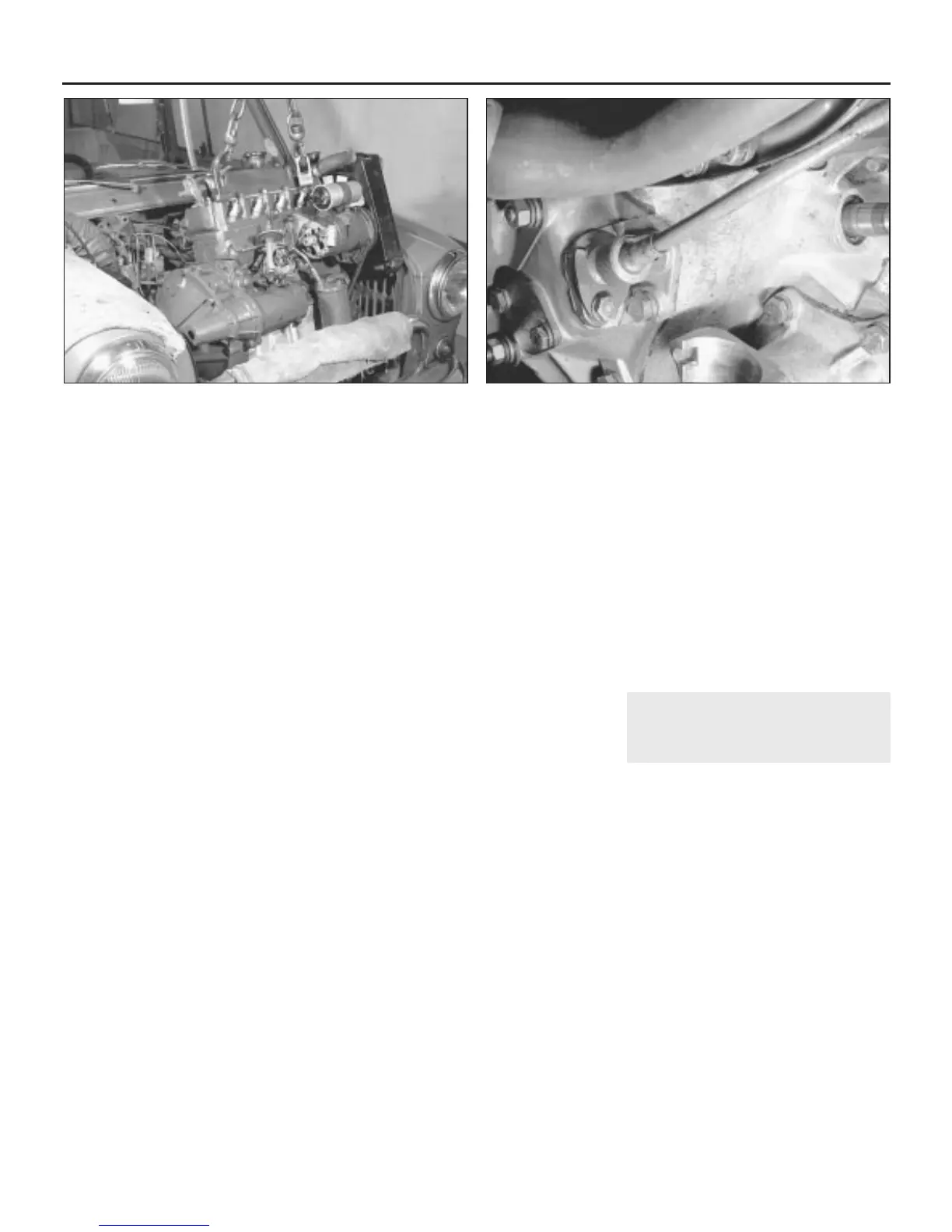
44 The engine/transmission can now be lifted
out. Tilt it backwards as it is lifted out to allow
the differential to clear the rear of the
subframe. When the unit is halfway out or
when sufficient clearance exists, unscrew the
speedometer cable knurled retaining nut and
lift the cable off the housing (see
illustrations). On fuel injection engines,
disconnect the wiring connectors from the
PTC heater and coolant temperature sensor
situated on the underside of the inlet manifold.
Release the wiring harness from any relevant
retaining clips.
45 Now completely remove the power unit
from the vehicle and position it on a bench or
clean floor for separation (see illustration).
Refitting
46 Refitting is the reverse sequence to
removal, following where necessary the
instructions given in the other Chapters of this
manual. Note the following additional points:
a) Tighten all nuts and bolts to the specified
torque wrench settings (where given).
b) On models fitted with offset sphere inner
driveshaft joints, ensure that the joint
circlips are properly located in their
grooves, then apply a smear of graphite-
based grease to the splines, and locate
the joints in the transmission. Push them
firmly into position, and check they are
securely retained by the circlips.
c) Ensure that all wiring harnesses are
properly routed, and are retained by any
necessary cable-ties or clips.
d) On automatic transmission models, adjust
the selector cable as described in
Chapter 7B, Section 6.
e) On models fitted with a vacuum servo
unit, refit the brake master cylinder as
described in Chapter 9.
f) Tighten all hose clips securely, and refill
the cooling system as described in
Chapter 1.
g) Fit a new oil filter and fill the engine with
fresh oil as described in Chapter 1.
h) On completion, reconnect the battery,
and adjust the accelerator cable as
described in Chapter 4A or B as
applicable.
4 Engine/transmission (with
front subframe) - removal and
refitting
4
Note: After disconnecting all the relevant
components, the body can be lifted up at the
front by four strong people and wheeled away,
or the body can be lifted by block and tackle
and the engine/transmission and subframe
assembly rolled out from underneath. When
working on cars equipped with Hydrolastic
suspension, it will be necessary to have the
system depressurised by a Rover dealer
before commencing the removal procedure
(see Chapter 10 Section 2).
Removal
1 Begin by carrying out paragraphs 1 to 24,
and 27 to 33 inclusive of the previous Section,
ignoring references to manual or automatic
transmission where these are not applicable.
2 Refer to Chapter 4C if necessary and
remove the complete exhaust system from
the car.
3 Undo and remove the knurled nut securing
the speedometer cable to its housing on the
left-hand side of the transmission. Withdraw
the cable from the housing.
2B•6 Engine removal and overhaul procedures
3.44a Lift the engine/transmission out of the engine bay . . . 3.44b . . . until sufficient clearance exists to disconnect the
speedometer cable
 Loading...