4 Remove the brake master cylinder filler cap
and place a piece of polythene over the filler
neck. Now securely refit the cap. This will help
prevent loss of fluid when the hydraulic pipes
are disconnected.
5 On models equipped with a single line
braking system undo and remove the brake
hydraulic pipe to the front wheels at the three-
way connector on the bulkhead. Where a dual
line or split braking system is fitted, undo and
remove the hydraulic pipes to the front wheels
at the pressure differential warning actuator or
the pressure reducing valve according to
system type. In all cases plug or tape over the
pipe ends after removal to prevent dirt ingress.
6 If the brake lights are operated by a
hydraulic pressure switch, disconnect the
electrical leads at the switch, which is located
on the right-hand side of the subframe.
7 Slacken the clip and detach the brake servo
vacuum hose (where fitted) at the union on the
inlet manifold.
8 On models fitted with rubber cone
suspension, remove the front shock
absorbers as described in Chapter 10.
9 On cars fitted with Hydrolastic suspension,
undo and remove the displacer unit hoses at
the transfer pipe unions.
10 Now refit the roadwheels and lower the
car to the ground.
11 From inside the car lift up the carpets and
undo and remove the two bolts each side
securing the rear of the subframe or subframe
mounting to the floor.
12 At the front of the car undo and remove
the bolt that secures each side of the
subframe or subframe mounting to the body.
13 On early models knock back the locking
plate tabs from the two bolts (or nuts) on
either side of the engine compartment which
secure the subframe towers to the bulkhead
crossmember.
14 Now undo and remove the bolts or nuts.
On later models undo and remove the large
hexagon-headed plug that is fitted in place of
the early bolt or stud mounting.
15 Make a final check that all cables, pipes
and hoses have been disconnected and that
all removed parts are clear of the engine and
subframe.
16 Support the front of the subframe and the
rear of the transmission casing with blocks of
wood or jacks and lift the body at the front
until it is clear of the engine. Take care that all
components are clear when lifting the body
and ensure that the radiator matrix is not
damaged.
17 Now wheel the body away from the
subframe or roll the subframe out from
underneath, whichever is more convenient.
Refitting
18 Refitting is the reverse sequence to
removal, following where necessary the
instructions given in the other Chapters of this
manual. Note the following additional points:
a) Tighten all nuts and bolts to the specified
torque wrench settings (where given).
b) Ensure that all wiring harnesses are
properly routed, and are retained by any
necessary cable-ties or clips.
c) Adjust the accelerator cable as described
in Chapter 4A or B as applicable.
d) On automatic transmission models, adjust
the selector cable as described in
Chapter 7B, Section 6.
e) Tighten all hose clips securely, and refill
the cooling system as described in
Chapter 1.
f) Fit a new oil filter and fill the engine with
fresh oil as described in Chapter 1.
g) Bleed the brake hydraulic system on
completion as described in Chapter 9.
Where Hydrolastic suspension is fitted it
will be necessary to have the system
repressurised by a Rover dealer
5 Engine and manual
transmission - separation and
reconnection
3
Separation
1 Remove the engine/transmission assembly
from the car as described in Section 3.
Alternatively, if the unit has been removed
complete with front subframe, undo the
engine/transmission mounting attachments
and lift the assembly from the subframe using
suitable lifting tackle. Position the
engine/transmission on the bench and
proceed as follows.
2 If not already done, drain the
engine/transmission oil as described in
Chapter 1.
3 Undo and remove the retaining bolts and lift
off the flywheel housing cover and, if still in
place, the starter motor (see illustration).
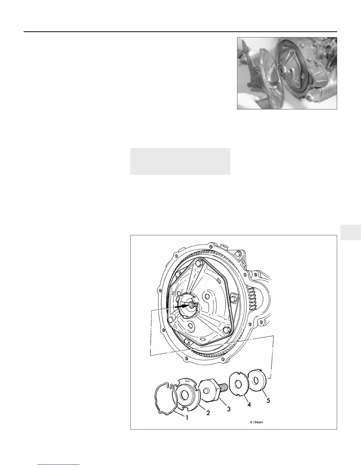
4 Where applicable, withdraw the wire
retaining clips and lift away the clutch thrust
plate from the centre of the diaphragm spring
housing (see illustration).
5 Rotate the flywheel until the timing marks
on the flywheel periphery are at approximately
the 3 o’clock position. This will prevent the
primary gear retaining U-shaped washer from
becoming dislodged as the flywheel is
removed.
Engine removal and overhaul procedures 2B•7
2B
5.3 Removing the flywheel housing cover
5.4 Clutch thrust plate and flywheel
securing bolt assemblies
1 Circlip
2 Release bearing thrust
plate
3 Flywheel retaining
bolt
4 Lockwasher
5 Keyed washer
 Loading...