6 Using a punch or small chisel, knock back
the lockwasher securing the large flywheel
retaining bolt in the centre of the flywheel.
7 With a large socket and extension handle,
undo and remove the flywheel retaining bolt.
Insert a screwdriver between the flywheel ring
gear teeth and housing to prevent the flywheel
from turning while the bolt is removed. Also
have an assistant support the engine, as this
bolt will be tight requiring considerable
leverage to remove it. When the bolt is
removed, prise out the keyed locating washer
from the end of the flywheel and crankshaft.
8 Where the bolt which retains the flywheel to
the crankshaft has been secured with thread-
locking compound or an encapsulated type of
bolt is used, then prior to refitting, all threads
in the crankshaft must be thoroughly cleaned.
Preferably, this should be done by using a tap
of the appropriate size. Discard the old
retaining bolt, and use only a new
encapsulated bolt incorporating a thread-
locking compound patch on refitting.
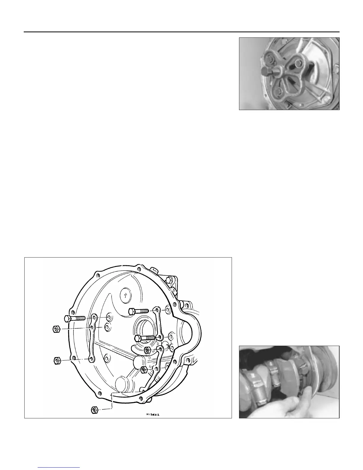
9 The flywheel is a taper fit on the end of the
crankshaft and a special puller will be needed
to remove it. This puller is Rover special tool
18G304 and adapter 18G304M for models
without the later type verto clutch assembly,
or 18G1381 for models with a verto type
clutch (see Chapter 6 for identification of the
two clutch types, if necessary). Note that
there are a number of similar pullers readily
obtainable from accessory shops or tool hire
outlets if the manufacturer’s tool is not
available (see illustration).
10 Position the puller with the three studs or
bolts inserted through the holes in the spring
housing (non-verto type) and screwed into the
flywheel securely. Do not tighten the studs/
bolts or the clutch disc may be damaged. Fit
the thrust pad of the puller to the end of the
crankshaft and then tighten the puller centre
bolt. Prevent the flywheel from turning using a
screwdriver inserted into the ring gear teeth.
11 Continue tightening the centre bolt of the
puller until the flywheel breaks free from the
taper. It is quite likely that the flywheel will be
extremely tight requiring a great deal of effort
to free it. If this is the case sharply strike the
puller centre bolt with a medium hammer. This
should “shock” the flywheel off the taper.
Take care when doing this as the flywheel
may spring off and land on your feet!
12 Once the taper is released the complete
clutch and flywheel assembly can be lifted off
the end of the crankshaft.
13 With the flywheel and clutch removed the
flywheel housing can be separated from the
engine/transmission casing as follows.
14 If a breather is fitted to the top of the
housing undo and remove the retaining bolts
and lift off the breather assembly.
15 Knock back the tabs on the lockwashers
inside the housing.
16 Undo and remove the nine nuts from the
studs on the transmission casing (see
illustration).
17 Undo and remove the six bolts from the
cylinder block. Note the positions from which
the shorter bolts are removed.
18 The housing can now be carefully pulled
off. Note that as the housing is withdrawn a
small quantity of oil will be released so have
some old rags or a small container handy.
19 With the flywheel and flywheel housing
removed, undo and remove the flange nuts,
bolts and spring washers securing the engine
to the transmission.
20 Undo and remove the bolts securing the
radiator lower mounting bracket to the engine
mounting bracket.
21 Using a crane, or hoist and lifting slings,
carefully lift the engine off the transmission
casing. It may be necessary to tap the
transmission casing downwards with a rubber
or hide mallet to break the seal between the
two mating faces.
22 With the engine removed, cover the top of
the transmission to prevent dirt ingress.
Reconnection
Note: Before reconnecting the engine and
transmission, refer to Chapter 7A, Section 6
and adjust the endfloat of the transfer gears
(primary gear and idler gear). Then proceed as
described below.
23 Carefully scrape away any remaining
traces of old gasket from the
engine/transmission mating faces and
flywheel housing joint.
24 Lightly smear the upper sides of the
engine/transmission joint gaskets with jointing
compound and place them in position on the
engine mating face.
25 Apply a bead of RTV sealant to all the
mating surfaces of the front oil seal, then
place seal in position between the front main
bearing cap and engine front plate (see
illustration).
2B•8 Engine removal and overhaul procedures
5.9 Using a commercially available puller
to release the flywheel taper
5.25 Fitting a new front oil seal . . .5.16 Flywheel housing attachments
 Loading...