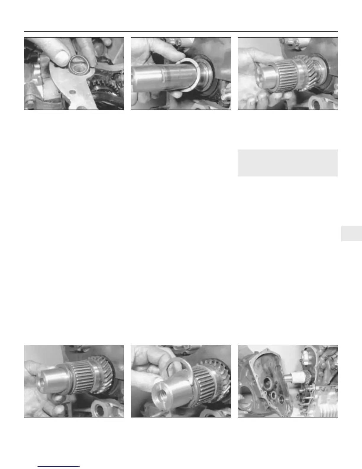
26 Locate the oil supply O-ring into its
groove in the transmission casing face, and if
necessary retain it in place with a trace of
grease (see illustration).
27 Using suitable lifting gear and with the
help of an assistant, carefully lower the engine
onto the transmission casing. Have your
assistant guide the engine, and lower it very
slowly, as it is easy to dislodge the gaskets.
28 With the engine in position, refit and fully
tighten the retaining nuts, bolts and spring
washers, and refit the radiator lower mounting
bolts.
29 Refit the primary gear thrustwasher to the
end of the crankshaft with its chamfered side
toward the crankshaft flange (see
illustration).
30 Slide on the primary gear (see
illustration) and then turn the crankshaft until
No 1 piston at TDC (refer to Part A, Section 3).
31 Refit the primary gear retaining ring and
then secure the assembly in position with the
C-shaped washer (see illustrations).
32 Refit the idler gear to its bearings in the
transmission casing, turning it slightly to mesh
with the other two gears as it is installed.
Ensure that both the thrustwashers are in
position, one each side of the idler gear: if the
later type gear is being fitted, the longer boss
goes toward the transmission casing.
33 Place a new joint gasket over the studs on
the transmission casing.
34 Before fitting the flywheel housing, make
sure that a new flywheel housing oil seal has
been fitted (see Part A, Section 9), and cover
the splines of the primary gear with the
special thin sleeve of Rover special tool
18G570. Alternatively, wrap tin foil or masking
tape tightly over the splines to avoid
damaging the seal. Lubricate the lip of the oil
seal prior to fitting.
35 Carefully refit the flywheel housing, taking
care that the rollers on the first motion shaft
bearing enter their outer race squarely. On no
account force the housing. If it does not easily
push fully home, turn the bearing slightly and
try again. Two or three attempts may be
needed (see illustration).
36 Refit new locking tabs, followed by the
housing retaining nuts and bolts to their
correct locations. Tighten the fixings to the
specified torque and bend over the locktabs.
37 Carefully clean the mating tapers in the
flywheel and on the end of the crankshaft, and
make quite certain there are no traces of oil,
grease, or dirt present.
38 Refit the flywheel on the end of the
crankshaft with the 1/4 TDC markings at the
top and then refit the driving washer which
positively locates the flywheel.
39 Fit a new lockwasher under the head of the
flywheel securing bolt. Remember to use only a
new encapsulated bolt incorporating a thread-
locking compound if that type of bolt was
removed. Insert the bolt in the centre of the
flywheel and tighten it to the specified torque.
40 Tap down the side of the lockwasher
against the driving plate, and tap up the other
side of the washer against the retaining bolt
head.
41 Refit the thrust plate and secure it in
position with the circular retaining spring.
42 Now refit the flywheel housing cover and
fully tighten the retaining bolts. Refit the
starter motor if appropriate at this stage.
6 Engine and automatic
transmission - separation and
reconnection
3
Separation
1 Remove the engine/transmission assembly
from the car as described in Section 3.
Alternatively, if the unit has been removed
complete with front subframe, undo the
engine/transmission mounting attachments
and lift the assembly from the subframe using
suitable lifting tackle. Position the engine/
transmission on the bench and proceed as
follows.
2 If not already done, drain the engine/
transmission oil as described in Chapter 1.
3 Undo and remove the retaining bolts and lift
off the torque converter housing cover and, if
still in place, the starter motor.
4 Undo and remove the retaining nuts and
bolts and take off the converter housing cover.
5 Undo and remove the five retaining bolts
and lift off the low pressure valve assembly
from its location beneath the torque converter
(see illustration).
6 Using a socket and bar, undo and remove
the converter input gear retaining nut. Use a
large screwdriver inserted through the hole in
the top of the converter housing and engaged
with the ring gear teeth to prevent the torque
converter from turning.
Engine removal and overhaul procedures 2B•9
2B
5.26 . . . and a new O-ring to the
transmission casing joint face
5.29 Position the primary gear
thrustwasher on the crankshaft
5.30 Slide on the primary gear . . .
5.31a . . . followed by the retaining ring . . . 5.31b . . . and the C-shaped washer 5.35 Refitting the flywheel housing
 Loading...