7 Knock back the locktabs, and undo and
remove three equally spaced bolts from the
centre of the converter. Leave the other three
bolts in position.
8 Knock back the lockwasher securing the
large converter centre retaining bolt. Using a
large socket and bar, undo and remove the
torque converter centre bolt. Use a
screwdriver as previously described to
prevent the converter from turning.
9 Rotate the crankshaft until the timing marks
on the converter periphery are at
approximately the 3 o’clock position.
10 The torque converter is a taper fit on the
end of the crankshaft and it will be necessary
to obtain Rover special tool 18G1086 to
remove it. The tool is bolted to the torque
converter through the holes of the three
previously removed converter retaining bolts.
With the adapter in position on the end of the
crankshaft, tighten the tool centre bolt until
the torque converter breaks free of the taper,
and then lift it off the crankshaft.
11 Undo and remove the nuts, bolts and
washers securing the converter housing to the
engine and transmission casing.
12 Remove the selector bellcrank lever clevis
pin and nut, and lift off the bellcrank lever.
Remove the bellcrank lever pivot.
13 The converter housing can now be
carefully withdrawn.
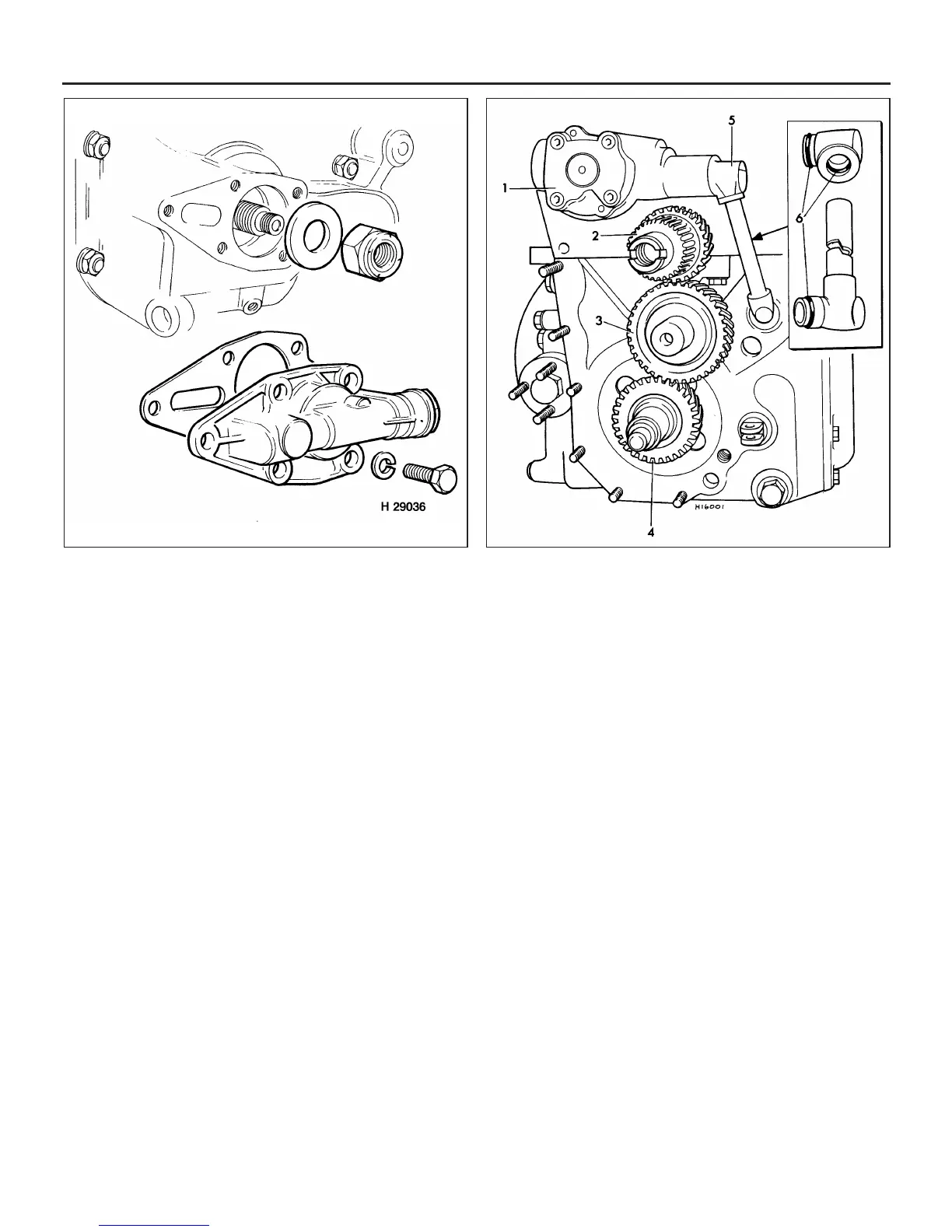
14 With the torque converter and housing
removed, carefully lever the main oil feed pipe
from the transmission and oil pump (see
illustration).
15 Undo and remove the two retaining bolts
and lift off the oil filter and housing assembly.
16 Unscrew the engine oil feed pipe union at
the adapter on the transmission casing.
17 Undo and remove the flange nuts, bolts
and spring washers securing the engine to the
transmission.
18 Undo and remove the bolts securing the
radiator lower mounting bracket to the engine
mounting adapter.
19 Using a crane, or hoist and lifting slings,
carefully lift the engine off the transmission
casing. It may be necessary to tap the
transmission casing downward with a rubber
or hide mallet to break the seal between the
two mating faces.
20 With the engine removed cover the top of
the transmission completely to prevent dirt
ingress.
Reconnection
Note: Before reconnecting the engine and
transmission, the endfloat of the transfer gears
(primary gear and idler gear) must be adjusted.
The procedure is the same as for manual
transmission models and is described in
Chapter 7A, Section 6. With the endfloat
adjusted, proceed as described below.
21 Carefully scrape away any remaining traces
of old gasket from the engine/transmission
mating faces and flywheel housing joint.
22 Lightly smear the upper sides of the
engine/transmission joint gaskets with jointing
compound and place them in position on the
engine mating face.
23 Apply a bead of RTV sealant to all the
mating surfaces of the front oil seal, then
place seal in position between the front main
bearing cap and engine front plate.
24 Using suitable lifting gear and with the
help of an assistant, carefully lower the engine
onto the transmission casing. Have your
assistant guide the engine, and lower it very
slowly, as it is easy to dislodge the gaskets.
25 With the engine in position, refit and fully
tighten the retaining nuts, bolts and spring
washers, and refit the radiator lower mounting
bolts.
26 Refit the engine oil feed pipe to the union
on the transmission casing.
27 Place a new gasket in position and refit
the oil filter assembly.
28 Using new O-rings where necessary,
carefully push the oil feed pipe into
engagement with the oil pump and
transmission casing orifice.
29 Place the converter output gear
thrustwasher over the end of the crankshaft,
with its chamfered face toward the crankshaft
flange.
2B•10 Engine removal and overhaul procedures
6.5 Low pressure valve assembly and input gear retaining nut -
automatic transmission models
6.14 End view of the automatic transmission transfer gears with
the converter housing removed
1 Main oil pump
2 Converter output gear
3 Idler gear
4 Input gear
5 Oil feed pipe
6 Sealing rings
 Loading...