30 Now slide on the output gear. Turn the
crankshaft until No 1 piston is at TDC (refer to
Part A, Section 3) then refit the output gear
retaining ring and C-shaped washer.
31 With the thrustwashers located over each
side of the idler gear, insert the gear into its
needle roller bearing.
32 Ensure that the mating faces of the
engine/transmission and converter housing
are clean, and then position a new gasket
over the studs on the transmission.
33 Before fitting the converter housing, make
sure that a new converter housing oil seal has
been fitted (see Part A, Section 9), and cover
the splines of the converter output gear with
the special thin sleeve of Rover special tool
18G1098. Alternatively, wrap tin foil or
masking tape tightly over the splines to avoid
damaging the seal. Lubricate the lip of the oil
seal prior to fitting.
34 Now carefully refit the converter housing,
pushing it squarely home over the
transmission casting studs. Refit the retaining
nuts and bolts, tightened to the specified
torque.
35 Refit the selector bellcrank lever pivot,
lever, clevis pin and nut.
36 Before fitting the torque converter, it will
be first necessary to refit the three central
bolts removed to allow the special converter
removal tool to be used during dismantling.
Then remove each pair of bolts in turn from
the converter centre and fit new locking
plates. Tighten the six bolts to the specified
torque wrench setting and bend over the lock
tabs. On no account remove all six bolts at any
one time. Then, with No 1 and 4 pistons still at
the TDC position, slide the torque converter
onto the end of the crankshaft, with the timing
marks uppermost. Refit the driving collar, a
new lockwasher and the retaining bolt.
Tighten the retaining bolt to the torque given
in the Specifications, and then knock back the
lockwasher.
37 Now refit and fully tighten the input gear
retaining nut.
38 Position a new gasket on the transmission
casing and refit the low pressure valve
assembly.
39 Finally refit the converter housing cover
and the starter motor.
7 Engine overhaul - preliminary
information
It is much easier to dismantle and work on
the engine if it is mounted on a portable
engine stand. These stands can often be hired
from a tool hire shop.
If a stand is not available, it is possible to
dismantle the engine with it suitably
supported on a sturdy, workbench or on the
floor. Be careful not to tip or drop the engine
when working without a stand.
If you intend to obtain a reconditioned
engine, all ancillaries must be removed first, to
be transferred to the replacement engine (just
as they will if you are doing a complete engine
overhaul yourself). These components include
the following:
a) Dynamo/alternator mounting brackets.
b) Engine/transmission mountings and
brackets (Part A of this Chapter).
c) Tappet block side covers - where fitted
(Section 9).
d) The ignition system and HT components
including all sensors, distributor cap and
rotor arm, HT leads and spark plugs
(Chapters 1 and 5B).
e) Distributor driveshaft (Part A of this Chapter).
f) All electrical switches and sensors.
g) Emission control equipment - where
applicable (Chapter 4C).
h) Thermostat and housing, water pump,
heater control valve (Chapter 3).
i) Mechanical fuel pump - carburettor
engines only (Chapter 4A).
j) Carburettor/fuel injection system
components (Chapter 4A and 4B).
k) Inlet and exhaust manifolds (Chapter 4A,
4B and 4C).
l) Oil pump (Section 10).
m)Oil filter housing and delivery pipe (Part A
of this Chapter).
n) Oil filter (Chapter 1).
Note: When removing the external
components from the engine, pay close
attention to details that may be helpful or
important during refitting. Note the fitting
positions of gaskets, seals, washers, bolts and
other small items.
If you are obtaining a “short” engine
(cylinder block, crankshaft, pistons, camshaft
and tappets, and connecting rods all
assembled), then the cylinder head, timing
chain (together with tensioner, sprockets and
cover) will have to be removed also.
If a complete overhaul is planned, the
engine can be dismantled in the order given
below, referring to Part A of this Chapter
unless otherwise stated.
a) Inlet and exhaust manifolds (Chapter 4A
or 4B).
b) Distributor driveshaft.
c) Timing chain, sprockets and tensioner.
d) Cylinder head.
e) Camshaft and tappets (Section 9).
f) Oil pressure relief valve.
g) Oil filter housing and delivery pipe.
h) Oil pump (Section 10).
i) Piston/connecting rod assemblies
(Section 11).
j) Crankshaft (Section 12).
8 Cylinder head - dismantling,
cleaning, inspection and
reassembly
3
Note: New and reconditioned cylinder heads
are available from the manufacturer, and from
engine overhaul specialists. Be aware that
some specialist tools are required for the
dismantling and inspection procedures, and
new components may not be readily available.
It may therefore be more practical and
economical for the home mechanic to
purchase a reconditioned head, rather than
dismantle, inspect and recondition the original
head.
Dismantling
1 Remove the cylinder head as described in
Part A of this Chapter.
2 If not already done, remove the inlet and
exhaust manifolds with reference to the
relevant Part of Chapter 4.
3 With a pair of pliers remove the spring clips
(where fitted) holding the two halves of the
split collets together.
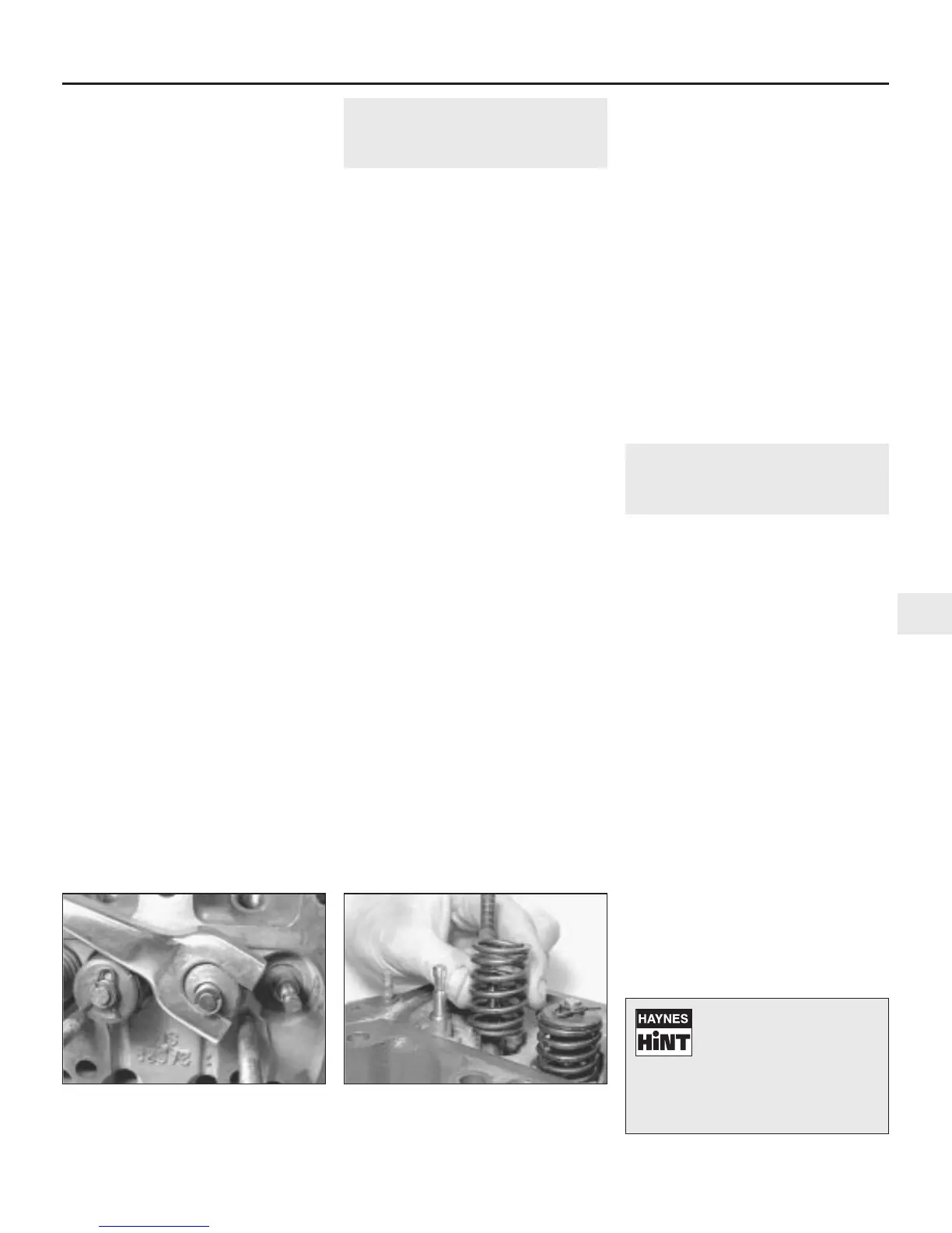
4 Using a valve spring compressor, compress
each valve spring in turn until the split collets
can be removed. Release the compressor,
and lift off the spring retainer, valve guide
shield (early models) and the spring. Where
fitted, slide the oil seal off the valve stem.
Note: On 1275 cc engines the oil seal is
positioned over the valve guide. On Cooper S
models double valve springs are used. (see
illustrations).
Engine removal and overhaul procedures 2B•11
2B
8.4a Compress the valve springs with a
spring compressor and lift off the split
collets . . .
8.4b . . . Then remove the compressor,
valve cap and spring
If, when the valve spring
compressor is screwed
down, the spring retainer
refuses to free and expose
the split collets, gently tap the top of
the tool, directly over the retainer, with
a light hammer. This will free the
retainer.
 Loading...