and refit the big-end bearing caps, using the
marks made or noted on removal to ensure
that they are fitted the correct way around.
8 Tighten the bearing cap nuts or bolts to the
specified torque. Take care not to disturb the
Plastigage, nor rotate the connecting rod
during the tightening sequence.
9 Dismantle the assemblies without rotating
the connecting rods. Use the scale printed on
the Plastigage envelope to obtain the big-end
bearing running clearance. Use the correct
scale as both imperial and metric are printed.
10 If the clearance is significantly different
from that given in the Specifications, the
bearing shells may be the wrong size (or
excessively worn, if the original shells are
being re-used). Make sure that no dirt or oil
was trapped between the bearing shells and
the caps or block when the clearance was
measured. If the Plastigage was wider at one
end than at the other, the crankshaft journal
may be tapered.
11 Before condemning the components
concerned, refer to your Rover dealer or engine
reconditioning specialist for their advice on the
best course of action to be taken.
12 On completion, carefully scrape away all
traces of the Plastigage material from the
crankshaft and bearing shells. Use your
fingernail, or some other object which is
unlikely to score the bearing surfaces.
Piston/connecting rod
assemblies - final refitting
13 Ensure that the bearing shells are correctly
fitted as described earlier. Wipe dry the shells
and connecting rods with a clean cloth.
14 Lubricate the cylinder bores, the pistons,
and piston rings, then lay out each
piston/connecting rod assembly in its
respective position.
15 Start with assembly No 1. Make sure that
the piston rings are still spaced as described
in Section 16, then clamp them in position
with a piston ring compressor.
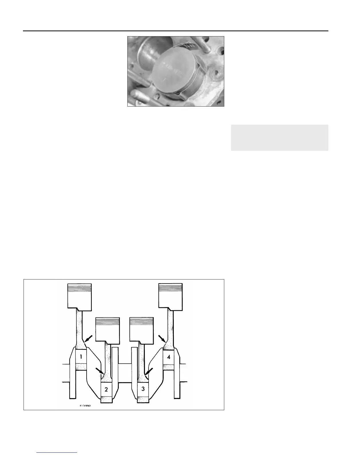
16 Insert the piston/connecting rod assembly
into the top of cylinder No 1. Ensure that it is
the correct piston/connecting rod assembly
for that particular bore, that the connecting rod
is the right way round, and that the front of the
piston is towards the front of the engine. Using
a block of wood or hammer handle against the
piston crown, tap the assembly into the
cylinder until the piston crown is flush with the
top of the cylinder (see illustration).
17 Ensure that the bearing shell is still
correctly installed. Liberally lubricate the
crankpin and both bearing shells. Taking care
not to mark the cylinder bores, pull the
piston/connecting rod assembly down the
bore and onto the crankpin. As the big-end
bosses on the connecting rods are offset, it
will be obvious if they have been inserted the
wrong way round because they will not fit over
the crankpin. The centre two rods must be
fitted with their offset bosses facing away
from the centre main bearing, and the
connecting rods at each extremity of the
engine must be fitted with their offset bosses
facing inwards (see illustration). Fit the big-
end cap and retaining bolts with the one-
piece locking tab under them (where
applicable) and tighten the bolts to the
specified torque. On 1275 cc engines the
arrangement is slightly different, the caps
being retained by nuts.
18 Once the bearing cap retaining nuts or
bolts have been correctly tightened, rotate the
crankshaft. Check that it turns freely; some
stiffness is to be expected if new components
have been fitted, but there should be no signs
of binding or tight spots.
19 Refit the remaining three piston/
connecting rod assemblies in the same way.
19 Engine - initial start-up after
overhaul and reassembly
2
1 Refit the remainder of the engine
components in the order listed in Section 15
of this Chapter, referring to Part A where
necessary. Reconnect the engine to the
transmission (Section 5 or 6 as applicable),
then refit the power unit to the car as
described in Section 3.
2 With the engine/transmission refitted,
double-check the engine oil and coolant
levels. Make a final check that everything has
been reconnected, and that there are no tools
or rags left in the engine compartment.
3 Remove the spark plugs. Disable the
ignition system by disconnecting the ignition
HT coil lead from the distributor cap, and
earthing it on the cylinder block. Use a jumper
lead or similar wire to make a good
connection.
4 Turn the engine on the starter until the oil
pressure warning light goes out. Refit the
spark plugs, and reconnect the spark plug and
distributor (HT) leads, referring to Chapter 1 for
further information.
5 Start the engine, noting that this may take a
little longer than usual, due to the fuel system
components having been disturbed.
6 While the engine is idling, check for fuel,
water and oil leaks. Don’t be alarmed if there
are some odd smells and smoke from parts
getting hot and burning off oil deposits.
7 Assuming all is well, keep the engine idling
until hot water is felt circulating through the
top hose, then switch off the engine.
8 Check the ignition timing and the idle speed
settings (as appropriate), then switch the
engine off.
9 After a few minutes, recheck the oil and
coolant levels as described in Chapter 1, and
top-up as necessary.
10 If new pistons, rings or crankshaft
bearings have been fitted, the engine must be
treated as new, and run-in for the first 500
miles (800 km). Do not operate the engine at
full-throttle, or allow it to labour at low engine
speeds in any gear. It is recommended that
the oil and filter be changed at the end of this
period.
2B•22 Engine removal and overhaul procedures
18.16 Refitting a piston with a piston ring
clamp in position
18.17 The correct positions of the offsets on the connecting rod big-ends
 Loading...