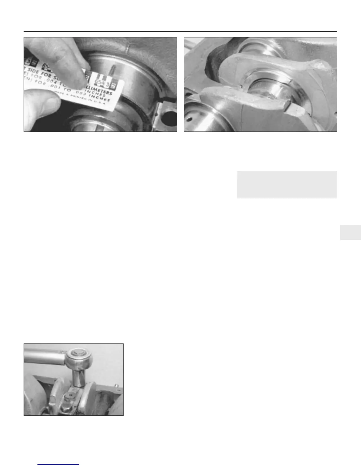
11 Compare the width of the crushed
Plastigage on each journal to the scale printed
on the Plastigage envelope to obtain the main
bearing running clearance (see illustration).
Use the correct scale as both imperial and
metric are printed. Compare the clearance
measured with the running clearance
dimension given in the Specifications.
12 If the clearance is significantly different
from that expected, the bearing shells may be
the wrong size (or excessively worn if the
original shells are being re-used). Before
deciding that the crankshaft is worn, make
sure that no dirt or oil was trapped between
the bearing shells and the caps or block when
the clearance was measured. If the Plastigage
was wider at one end than at the other, the
crankshaft journal may be tapered.
13 Before condemning the components
concerned, seek the advice of your Rover
dealer or suitable engine repair specialist.
They will also be able to inform as to the best
course of action and whether it is possible to
have the crankshaft journals reground or
whether renewal will be necessary.
14 Where necessary, obtain the correct size of
bearing shell and repeat the running clearance
checking procedure as described above.
15 On completion, carefully scrape away all
traces of the Plastigage material from the
crankshaft and bearing shells using a
fingernail or other object which is unlikely to
score the bearing surfaces.
Crankshaft - final refitting
16 Lift the crankshaft out of the crankcase.
Wipe the surfaces of the bearings in the
crankcase and the bearing caps.
17 Wipe the recesses either side of the
centre main bearings which locate the upper
halves of the thrustwashers.
18 Generously lubricate the crankshaft
journals and the upper and lower main
bearing shells with clean engine oil and
carefully place the crankshaft in position.
19 Introduce the upper halves of the
thrustwashers (the halves without tabs) into their
grooves on each side of the centre main bearing
(see illustration), rotating the crankshaft in the
direction towards the main bearing tabs (so that
the main bearing shells do not slide out). At the
same time feed the thrustwashers into their
locations with their oil grooves facing outwards
away from the bearing.
20 Ensure that all six tubular locating dowels
are still firmly in place, one on each side of the
upper halves of the three main bearings, and
then fit the main bearing caps in position
ensuring that they locate properly on the
dowels. The mating surfaces must be spotlessly
clean or the caps will not seat properly.
21 When refitting the centre main bearing
cap, ensure that the thrustwashers,
generously lubricated, are fitted with their oil
grooves facing outwards, and the locating tab
of each washer is in the slot in the bearing cap.
22 Refit the one-piece locking tabs over the
main bearing caps (where applicable) and refit
the main bearing cap bolts, screwing them up
finger-tight initially, then finally tightening to
the torque setting given in the Specifications
(see illustration).
23 Test the crankshaft for freedom of
rotation. Should it be very stiff to turn or
possess high spots, re-check the running
clearances as described above.
24 Carry out a check of the crankshaft
endfloat as described in Section 12. If the
thrust surfaces of the crankshaft have been
checked and new thrustwashers have been
fitted, then the endfloat should be within
specification.
25 When all is satisfactory, secure the main
bearing bolts by knocking up the locking tabs
(where applicable) with a small chisel.
18 Piston/connecting rod
assemblies - refitting and big-
end bearing clearance check
3
Note: At this point it is assumed that the
crankshaft has been refitted to the engine as
described in Section 17.
Big-end bearing running
clearance check
1 Clean the backs of the bearing shells, and
the bearing locations in both the connecting
rod and bearing cap.
2 Press the bearing shells into their locations,
ensuring that the tab on each shell engages in
the notch in the connecting rod and cap. If the
original bearing shells are being used for the
check, ensure that they are refitted in their
original locations.
3 As with the main bearings (Section 17), a
running clearance must exist between the big-
end crankpin and its bearing shells to allow oil
to circulate. There are two methods of
checking the running clearance as described
in the following paragraphs.
4 One method is to refit the big-end bearing
cap to the connecting rod, with the bearing
shells in place. With the cap retaining nuts or
bolts correctly tightened, use an internal
micrometer or vernier caliper to measure the
internal diameter of each assembled pair of
bearing shells. If the diameter of each
corresponding crankshaft journal is measured
and then subtracted from the bearing internal
diameter, the result will be the big-end
bearing running clearance.
5 The second, and more accurate method is
to use Plastigage (see Section 17).
6 Ensure that the bearing shells are correctly
fitted. Place a strand of Plastigage on each
(cleaned) crankpin journal.
7 Temporarily refit the (clean) piston/
connecting rod assemblies to the crankshaft,
Engine removal and overhaul procedures 2B•21
2B
17.22 Tighten the main bearing cap bolts
to the specified torque
17.11 Measuring the width of the deformed Plastigage using the
card gauge supplied
17.19 Refitting the crankshaft thrustwasher upper halves
 Loading...