8 Repeat the checking procedure for each
ring in the first cylinder, and then for the rings
in the remaining cylinders. Remember to keep
rings, pistons and cylinders matched up.
9 Once the ring end gaps have been checked
and if necessary corrected, the rings can be
fitted to the pistons.
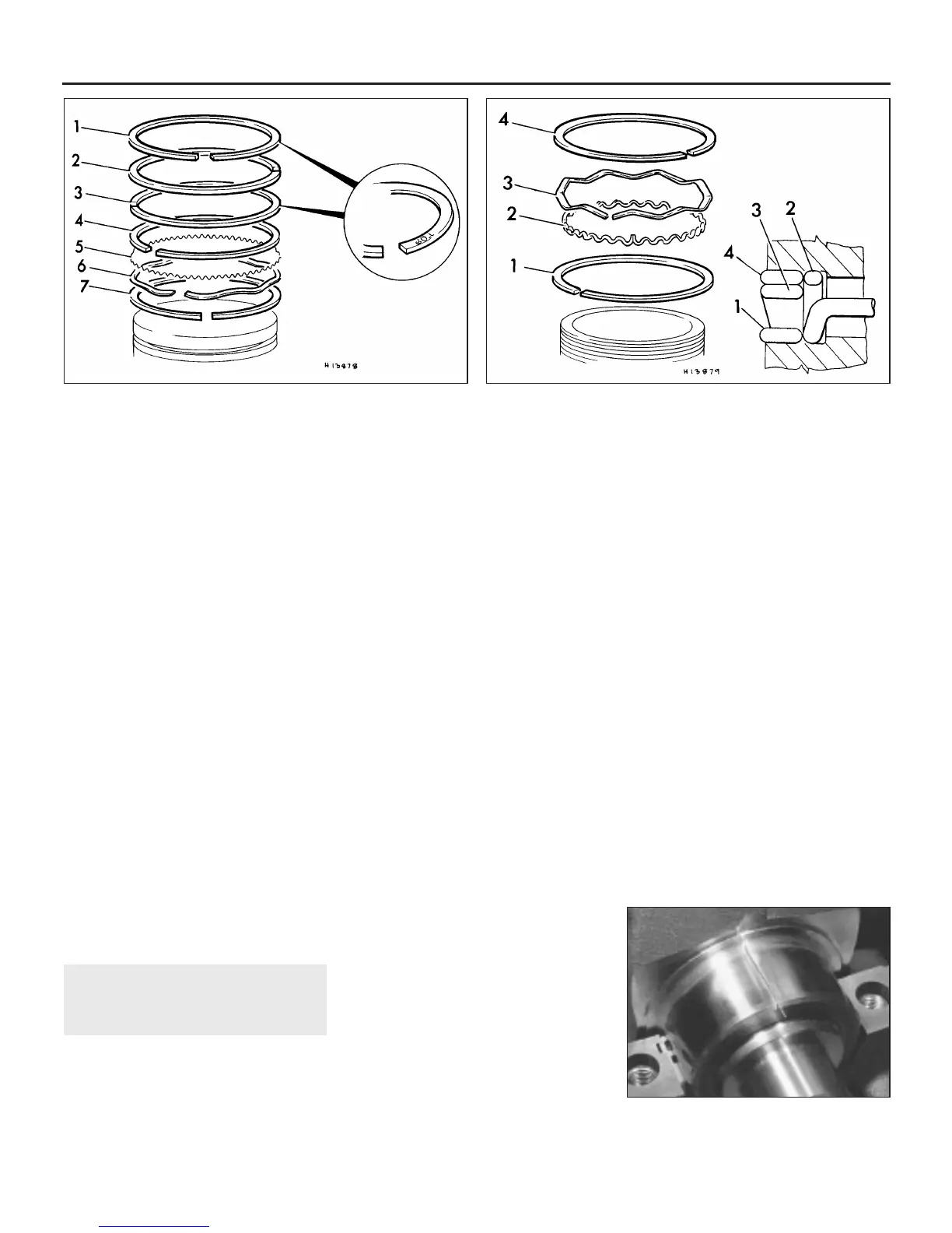
10 Fit the piston rings using the same
technique as for removal. Fit the bottom (oil
control) ring first, and work up. When fitting a
three piece oil control ring, first insert the
expander and position its gap in line with the
centre of the gudgeon pin. Fit the scraper
rings with their gaps positioned either side of
the expander gap. Where the oil control
scraper is of one-piece type, position its gap
180° from the expander gap. Ensure that the
second and third compression rings are fitted
the correct way up, with their identification
mark (either a “T” or the word “TOP” stamped
on the ring surface) at the top (see
illustrations). Carefully examine all rings for
this mark before fitting. Arrange the gaps of
the compression rings equally around the
piston. Note: Always follow any instructions
supplied with the new piston ring sets -
different manufacturers may specify different
procedures. Do not mix up the top and
second compression rings, as they have
different cross-sections.
17 Crankshaft - refitting and
running clearance check
3
1 Crankshaft refitting is the first stage of
engine reassembly following overhaul. It is
assumed at this point that the cylinder
block/crankcase and crankshaft have been
cleaned, inspected and repaired or
reconditioned as necessary.
2 Position the cylinder block on a clean level
work surface, with the crankcase facing
upwards. Unbolt the bearing caps and
carefully release them from the crankcase; lay
them out in order to ensure correct
reassembly. If they’re still in place, remove the
old bearing shells from the caps and
crankcase and wipe out the inner surfaces
with a clean rag - they must be kept spotlessly
clean.
3 Clean the backs of the bearing shells and
insert them into position in the crankcase. If
the original bearing shells are being used for
the check, ensure that they are refitted in their
original locations. Press the shells home so
that the tangs engage in the recesses
provided. When fitting the rear main bearing
shell, it may be found that the cylinder block
oilway is offset from the corresponding hole in
the bearing shell. This condition is acceptable
as long as a 2.3 mm diameter steel rod can be
inserted into the exposed section of the hole.
4 Give the newly fitted bearing shells and the
crankshaft journals a final clean with a rag.
Check that the oil holes in the crankshaft are
free from dirt, as any left here will become
embedded in the new bearings when the
engine is started.
5 Carefully lay the crankshaft in the
crankcase taking care not to dislodge the
bearing shells.
Running clearance check
6 When the crankshaft and bearings are
fitted, a clearance must exist between them to
allow lubricant to circulate. This clearance is
impossible to check using feeler blades, so
Plastigage is used. This consists of a fine
thread of perfectly round plastic which is
compressed between the bearing shell and
the journal when the bearing caps are
tightened up. When the cap and shell is
removed, the plastic is deformed and can be
measured with a special card gauge supplied
with the kit. The running clearance is
determined from this gauge. The procedure
for using Plastigage is as follows.
7 Cut off three lengths of Plastigage (they
should be slightly shorter than the width of the
main bearings) and place one length on each
crankshaft journal axis (see illustration).
8 Wipe the inner surface of the bearing caps
and the backs of the lower bearing shells and
fit the three bearing shells to their caps. Press
the shells home so that the tangs engage in
the recesses provided.
9 Ensure that all six tubular locating dowels
are firmly in place, one on each side of the
upper halves of the three main bearings, and
then fit the main bearing caps in position
ensuring that they locate properly on the
dowels. Tighten their retaining bolts to the
specified torque. Take care not to disturb the
Plastigage and do not rotate the crankshaft at
any time during this operation.
10 Remove the main bearing caps again
taking great care not to disturb the Plastigage
or rotate the crankshaft.
2B•20 Engine removal and overhaul procedures
16.10a Piston ring identification - 850, 1000 and 1100 models
1 Chrome plated
compression ring
2 Taper compression ring
3 Taper compression ring
4 Top rail
5 Expander
6 Side spring
7 Bottom rail
16.10b Correct assembly of oil control ring - 1275 models
1 Bottom rail
2 Expander
3 Oil control ring rail
4 Top rail
17.7 Plastigage in place on main bearing
journal
 Loading...