5 To use unleaded petrol on earlier models,
conversion kits are available (consisting
basically of an exchange cylinder head known
as “Green Packs”), through Rover dealers.
Any vehicle which has had such a conversion
will have the letter “U” stamped between the
engine prefix and the start of the serial
number, and can use either unleaded or
leaded petrol without modification. Note:
Apart from any adjustment made during the
fitting of a “Green Pack” no alteration should
be made to the ignition timing or carburation
settings.
6 Models equipped with a catalytic converter
must be run on unleaded petrol only.
11 Carburettor - general
information
SU HS2 and HS4
The variable choke SU HS2 and HS4
carburettors are relatively simple instruments
and are basically the same irrespective of
type. They differ from most other carburettors
in that, instead of having a number of various
sized fixed jets for different conditions, only
one variable jet is fitted to deal with all
possible conditions.
The carburettor comprises four main
assemblies; these are the carburettor body,
the piston and dashpot assembly, the jet
assembly and the float chamber. Fuel is
carried from the float chamber to the base of
the jet head by a nylon pipe, the float chamber
being secured to the carburettor body by a
horizontally positioned bolt and spacing
washer.
The operation of the carburettor is as
follows. Air passing rapidly through the
carburettor creates a slight vacuum or
depression over the jet, causing fuel to be
drawn into the air stream, thus forming the
fuel/air mixture. The amount of fuel drawn
from the jet depends on the position of the
tapered carburettor needle. This moves up or
down the jet orifice according to engine load
or throttle opening, thus effectively altering
the size of the jet. This allows the right amount
of fuel to be delivered for the prevailing road
conditions.
The position of the tapered needle in the jet
is determined by engine vacuum. The shank
of the needle is held at its top end in a piston,
which slides up and down the dashpot, in
response to the degree of manifold vacuum.
This is directly controlled by the throttle. The
piston is necessary so that the depression
over the jet needed to draw fuel into the air
stream, can be kept approximately constant.
At slow engine speeds, the air entering the
carburettor would not be travelling fast
enough to create sufficient vacuum to draw
fuel from the jet. By allowing the piston to
partially restrict the opening through the
carburettor, the incoming air is speeded up,
causing an adequate depression over the jet.
With the throttle fully open, the full effect of
inlet manifold vacuum is felt by the piston,
which has an air bleed into the carburettor
venturi on the outside of the throttle. This
causes the piston to rise fully, bringing the
needle with it. With the throttle partially
closed, only slight inlet manifold vacuum is
felt by the piston (although on the engine side
of the throttle, the vacuum is now greater),
and the piston only rises slightly.
To prevent piston flutter, and to give a
richer mixture when the accelerator is
suddenly depressed, an oil damper and light
spring are located inside the dashpot.
For cold starting, when fuel enrichment is
necessary and very small amounts of air are
drawn into the carburettor, actuation of the
choke control causes the jet head to be
lowered, thus effectively increasing the jet
size.
The only portion of the piston assembly to
come into contact with the piston chamber or
dashpot is the actual central piston rod. All
the other parts of the piston assembly,
including the lower choke portion, have
sufficient clearances to prevent any direct
metal-to-metal contact, which is essential if
the carburettor is to work properly.
The correct level of the petrol in the
carburettor is determined by the level of the
float in the float chamber. When the level is
correct, the float rises and, by means of a
lever resting on top of it, closes the needle
valve in the cover of the float chamber. This
closes off the supply of fuel from the pump.
When the level in the float chamber drops, as
fuel is used in the carburettor, the float sinks.
As it does, the float needle comes away from
its seat so allowing more fuel to enter the float
chamber and restoring the correct level.
SU HIF44 and HIF38
The SU HIF44 and HIF38 carburettors are
fitted to 1990-on Cooper models, and 1992-on
1275 cc models with open-loop catalytic
converter respectively. These carburettors
operate in a similar way to the SU HS2 and
HS4 instruments described previously, but the
float chamber has been incorporated into the
main body of the carburettor, and a bi-metallic
strip is fitted to the jet adjusting (mixture)
screw mechanism; that is in order to
compensate for the varying fuel densities
which result from changes in fuel temperature.
12 Carburettor - removal and
refitting
2
Note: Observe the precautions in Section 1
before working on any component in the fuel
system.
SU HS2 and HS4 carburettors
Removal
1 Disconnect the battery negative lead.
2 Remove the air cleaner assembly as
described in Section 2.
3 Disconnect the distributor vacuum advance
pipe from the carburettor (where fitted).
4 Slacken the retaining clip screw and
withdraw the fuel inlet pipe from the top of the
float chamber. Plug the disconnected pipe
with a bolt or metal rod of suitable diameter.
5 Refer to Sections 3 and 5 and disconnect
the accelerator and choke cables from the
carburettor linkages.
6 Detach the throttle return spring from the
bracket on the exhaust manifold clamp. On
Cooper S models detach the throttle and
throttle linkage return springs from the heat
shield. On automatic transmission models
detach the governor control rod fork end from
the throttle lever
7 Detach the engine breather hose from the
carburettor (where fitted).
8 Undo and remove the two nuts which
secure the carburettor(s) to the inlet manifold
studs and recover the spring washers.
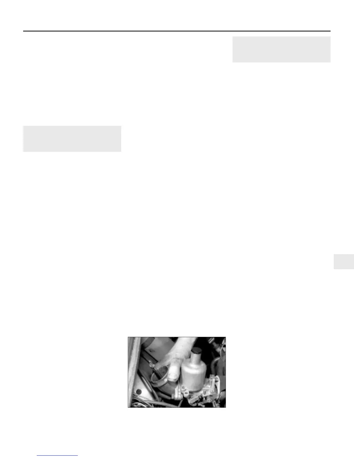
9 Lift the carburettor carefully off the inlet
manifold (see illustration). If twin
carburettors are being removed, lift off both
carburettors together to avoid damaging the
linkages that join the two carburettor spindles.
These can be removed after the carburettors
are lifted clear of the manifold studs.
Refitting
10 Refitting the carburettor(s) is the reverse
sequence to removal, noting the following
points:
a) Ensure that all mating surfaces are clean
and dry, and use new gaskets.
b) When refitting twin carburettors, ensure
that the linkages joining the two spindles
are in position, and that the operating
forks are engaged in the slots on the
carburettor spindles.
c) Tighten the carburettor nuts evenly and
progressively, to avoid possible distortion
of the mounting flange.
d) Refit the accelerator and choke cables
with reference to Sections 3 and 5.
SU HIF44 and HIF38
carburettors
Removal
11 Disconnect the battery negative lead.
12 Remove the air cleaner assembly as
described in Section 2.
13 On Cooper models, remove the
carburettor heat shield.
Fuel system - carburettor engines 4A•9
4A
12.9 Removing the SU HS2 carburettor
from the manifold
 Loading...