only obtainable as matched pairs and cannot
be interchanged. The piston and dashpot
assembly are in a satisfactory condition if the
piston, having been pushed right to the top of
the dashpot, will drop under its own weight
without any trace of binding.
27 Examine the float chamber needle valve
and seat next. After high mileage, it is quite
likely that a ridge will have formed on the face
of the needle. This could prevent the needle
valve from shutting off the fuel supply and
cause flooding of the carburettor. This is quite
a common occurrence on SU carburettors
and unless the needle and seat appear to be
in perfect condition, they should both be
renewed.
28 Finally, check the condition of the float. If
any signs of cracking or distortion are evident,
which may allow fuel to enter, renew the float.
29 If the carburettor has been completely
dismantled, begin reassembly by refitting the
piston lifting pin and spring into the
carburettor body and then refit the retaining
circlip.
30 Place the float chamber in position and
secure it in place, with the long retaining bolt
inserted through the side of the carburettor
body.
31 Refit the jet bearing, washer and locknut
finger-tight only. Do not refit the lock spring or
jet adjusting nut at this stage.
32 Refit the choke linkage and retaining pivot
bolt.
33 Insert the throttle spindle into the
carburettor body with the countersunk holes
in the spindle facing outwards. Insert the
throttle disc into the spindle, noting the
assembly markings made during dismantling.
Secure the disc to the spindle using new
retaining screws, but do not tighten them.
Snap the spindle open and shut to centralise
the disc and make sure that the disc does not
bind in the carburettor bore in any position. If
necessary reposition the disc slightly. Now
tighten the screws and spread their ends
enough to prevent them from turning.
34 Slide the spacing washer and throttle
lever onto the spindle, followed by the tab
washer and retaining nut. Tighten the nut and
bend over the tab washer.
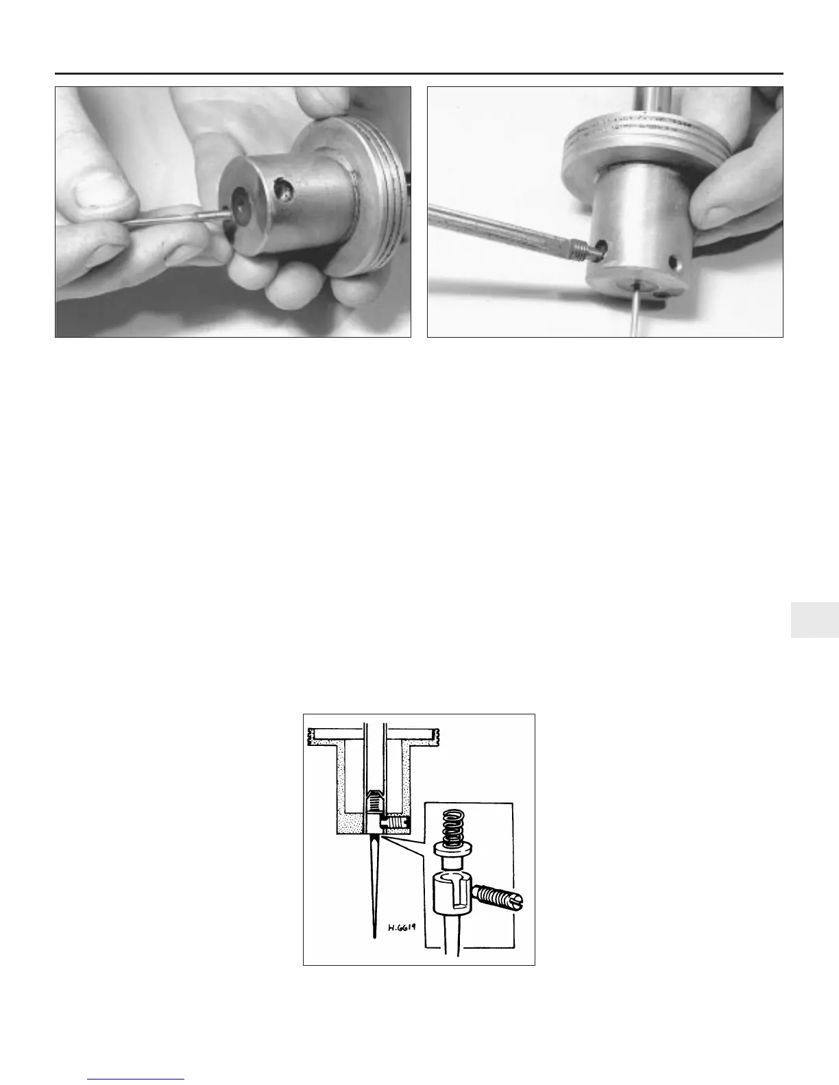
35 On carburettors with a fixed jet needle,
insert the needle into the piston, ensuring that
the shoulder on the shank of the needle is
flush with the underside of the piston. Refit
and fully tighten the sunken retaining screw
(see illustrations).
36 On carburettors equipped with a spring-
loaded needle, fit the spring and guide collar
to the needle and insert this assembly into the
piston. Position the guide collar so that it is
flush with the underside of the piston and
position the needle so that the small etch
mark is between the two piston transfer holes.
Secure the assembly with the sunken
retaining screw (see illustration).
37 If the jet housing has been removed, it will
now be necessary to centralise the jet as
follows.
38 With the jet bearing, washer and locknut
in position as described in paragraph 31, refit
the jet adjusting nut, without the lock spring,
and screw it up as far as it will go. Now slide
the jet assembly into the jet housing.
39 Carefully refit the piston and needle
assembly to the carburettor body, followed by
the spring and dashpot. Align the previously
made marks on the dashpot and carburettor
body and then refit the securing screws.
40 Slacken the jet bearing locknut and hold
the piston down using a pencil inserted
through the damper opening. Now tighten the
jet bearing locknut.
41 Lift the piston and allow it to fall under its
own weight. A definite metallic click should be
heard, as the piston falls and contacts the
bridge in the carburettor body.
42 Now fully lower the adjusting nut and note
whether the piston still falls freely. If not,
slacken the jet bearing locknut and repeat the
centring procedure. It may be necessary to
carry out the centring operation several times,
until the piston will fall freely with the adjusting
nut at the top and bottom of its travel.
43 With the jet correctly centralised, slide out
the jet assembly and unscrew the adjusting
nut. Now place the lock spring in position and
refit the adjusting nut and jet assembly.
Secure the jet link arm to the jet with the
screw or retaining clip.
44 The flexible jet fuel supply tube can now
be refitted to the base of the float chamber.
Ensure that the small rubber sealing washer,
nut and gland are in position on the tube and
that there is at least 5.0 mm of pipe protruding
through the washer. Push the tube into the
float chamber and tighten the union nut.
45 Refit the fuel cut-off needle and seat to
the float chamber cover. Place the float in
position and tap in the float hinge pin until
equal amounts of the pin are protruding either
side of the mounting lugs.
46 On early carburettors equipped with a
brass float, invert the float chamber cover so
that the needle valve is closed. It should now
just be possible to place a
5
⁄16 inch (8.0 mm)
diameter bar parallel to the float hinge pin and
Fuel system - carburettor engines 4A•13
4A
13.36 The spring-loaded needle assembly
fitted to the later SU HS4 carburettors
13.35a Refit the fixed jet needle to the piston . . . 13.35b . . . and secure with the retaining screw
 Loading...